Word2wiki bal gsq2
From Terasic Wiki
(→iOS APP Control ==) |
(→4-1 Connect Power Port) |
||
| (75 intermediate revisions not shown) | |||
| Line 1: | Line 1: | ||
| - | |||
| - | |||
| - | |||
| - | + | = <span style="color:#000080;">Chpater1 Introduction</span> = | |
| - | + | ||
| - | + | ||
| - | + | ||
| - | + | ||
| - | + | ||
| - | + | ||
| - | + | ||
| - | + | ||
| - | + | ||
| - | + | ||
| - | + | ||
| - | + | ||
| - | + | ||
| - | + | ||
| - | + | ||
| - | + | ||
| - | + | ||
| - | + | ||
| - | + | ||
| - | + | ||
| - | + | ||
| - | + | ||
| - | + | ||
| - | + | ||
| - | + | ||
| - | + | ||
| - | + | ||
| - | + | ||
| - | + | ||
| - | + | ||
| - | + | ||
| - | + | ||
| - | + | ||
| - | + | ||
| - | + | ||
| - | + | ||
| - | + | ||
| - | + | ||
| - | + | ||
| - | + | ||
| - | + | ||
| - | + | ||
| - | + | ||
| - | + | ||
| - | + | ||
| - | + | ||
| - | + | ||
| - | = | + | |
| Line 57: | Line 6: | ||
Based on the Terasic DE10-Nano SoC board platform, designed and manufactured independently by Terasic, the Self-Balancing Robot is a Multi-functional kit. It can implement advanced features like object following, obstacle avoidance and so on. It can also be remote controlled by an Android Smartphone’s APP and IR remote control. This guide describes in detail how users can make the robot work. | Based on the Terasic DE10-Nano SoC board platform, designed and manufactured independently by Terasic, the Self-Balancing Robot is a Multi-functional kit. It can implement advanced features like object following, obstacle avoidance and so on. It can also be remote controlled by an Android Smartphone’s APP and IR remote control. This guide describes in detail how users can make the robot work. | ||
| - | == | + | == 1-1 Package Contents == |
<span style="color:#666699;">'''Figure 1 -1'''</span>shows the package contents of the Self-Balancing Robot kit | <span style="color:#666699;">'''Figure 1 -1'''</span>shows the package contents of the Self-Balancing Robot kit | ||
| - | <div style="text-align:center;color:#000000;">[[Image: | + | <div style="text-align:center;color:#000000;">[[Image: BAL_02_Getting_Start_Guide_pic_1.jpg|700px]]</div> |
<div style="text-align:center;"> '''Figure 1‑1 Self-Balancing Robot package'''</div> | <div style="text-align:center;"> '''Figure 1‑1 Self-Balancing Robot package'''</div> | ||
| Line 81: | Line 30: | ||
⑦ Quick Start Guide | ⑦ Quick Start Guide | ||
| - | = | + | |
| + | = <span style="color:#000080;">Chpater2 Components and Functions</span> = | ||
| - | == | + | == 2-1 Parts and Functions == |
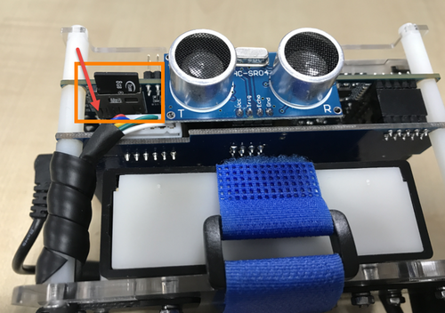
| - | This chapter will describe the robot’s components and the functions of the components, such as the ultrasonic module, motors, wheels and driving board power interface. Figure 2 -2, Figure 2 -3, Figure 2 - | + | This chapter will describe the robot’s components and the functions of the components, such as the ultrasonic module, motors, wheels and driving board power interface. Figure 2 -2, Figure 2 -3, Figure 2-4 and Figure 2-5 show all the components and specify their function. |
| - | <div style="text-align:center;color:#000000;">[[Image: | + | <div style="text-align:center;color:#000000;">[[Image: BAL_02_Getting_Start_Guide_pic_2.jpg|500px]]</div> |
<div style="text-align:center;"> '''Figure 2‑2 Self-Balancing Robot components'''</div> | <div style="text-align:center;"> '''Figure 2‑2 Self-Balancing Robot components'''</div> | ||
| Line 102: | Line 52: | ||
⑷ Wheels:implements the Self-Balancing robot’s movement. | ⑷ Wheels:implements the Self-Balancing robot’s movement. | ||
| - | <div style="text-align:center;color:#000000;">[[Image: | + | <div style="text-align:center;color:#000000;">[[Image: BAL_02_Getting_Start_Guide_pic_3.jpg|500px]]</div> |
<div style="text-align:center;"> '''Figure 2‑3 Self-Balancing Robot components'''</div> | <div style="text-align:center;"> '''Figure 2‑3 Self-Balancing Robot components'''</div> | ||
| Line 112: | Line 62: | ||
⑺ UART serial port:implement the communication between the board and PC when users develop their own design on the Self-Balancing robot. | ⑺ UART serial port:implement the communication between the board and PC when users develop their own design on the Self-Balancing robot. | ||
| - | <div style="text-align:center;color:#000000;">[[Image: | + | <div style="text-align:center;color:#000000;">[[Image: BAL_02_Getting_Start_Guide_pic_4.jpg|500px]]</div> |
<div style="text-align:center;"> '''Figure 2‑4 Self-Balancing Robot components'''</div> | <div style="text-align:center;"> '''Figure 2‑4 Self-Balancing Robot components'''</div> | ||
| Line 128: | Line 78: | ||
⒀ Battery power output plug:connect to motor driver board power port. | ⒀ Battery power output plug:connect to motor driver board power port. | ||
| - | <div style="text-align:center;color:#000000;"> | + | <div style="text-align:center;color:#000000;"> [[Image: BAL_02_Getting_Start_Guide_pic_5.jpg|500px]]</div> |
<div style="text-align:center;"> '''Figure 2‑5 Self-Balancing robot components'''</div> | <div style="text-align:center;"> '''Figure 2‑5 Self-Balancing robot components'''</div> | ||
| Line 140: | Line 90: | ||
| - | == | + | == 2-2 DE10-Nano Kit and Motor Driver Board == |
The Self-Balancing Robot control system consist two boards, Terasic DE10-Nano FPGA board and Motor Driver board (BAL board) as shown in Figure 2 -6. The FPGA on the DE10-Nano is responsible for all the functions of the balance and control system. The motor driver board receives the control signal from the de10-nano to control the motor rotation. There are also some sensors and communication devices on the motor driver board. These devices can provide the status data of the robot and external communication interface to FPGA. For detailed hardware information, please refer to 03_Hardware_Manual.pdf which can be found in the CD package. | The Self-Balancing Robot control system consist two boards, Terasic DE10-Nano FPGA board and Motor Driver board (BAL board) as shown in Figure 2 -6. The FPGA on the DE10-Nano is responsible for all the functions of the balance and control system. The motor driver board receives the control signal from the de10-nano to control the motor rotation. There are also some sensors and communication devices on the motor driver board. These devices can provide the status data of the robot and external communication interface to FPGA. For detailed hardware information, please refer to 03_Hardware_Manual.pdf which can be found in the CD package. | ||
| - | <div style="text-align:center;color:#ff0000;">[[Image: | + | <div style="text-align:center;color:#ff0000;">[[Image: BAL_02_Getting_Start_Guide_pic_6.png|500px]]</div> |
<div style="text-align:center;"> '''Figure 2‑6 DE10-Nano and Motor Driver Board'''</div> | <div style="text-align:center;"> '''Figure 2‑6 DE10-Nano and Motor Driver Board'''</div> | ||
| - | = | + | |
| + | = <span style="color:#000080;">Chpater3 Setup Elements</span> = | ||
| Line 154: | Line 105: | ||
This chapter will introduce the switches and buttons that can be set on the Self-Balancing Robot. It explains the meaning and function of the setting. | This chapter will introduce the switches and buttons that can be set on the Self-Balancing Robot. It explains the meaning and function of the setting. | ||
| - | == | + | == 3-1 Configuration Mode Switches == |
| Line 161: | Line 112: | ||
If user want to select ARM to control the robot, the MSEL[4:0] needs to switch to "01010" , as shown in Figure 3 -7. Thus, when the robot is power on, the FPGA will boot from the Micro SD card and run the Linux by ARM processor to control the robot. | If user want to select ARM to control the robot, the MSEL[4:0] needs to switch to "01010" , as shown in Figure 3 -7. Thus, when the robot is power on, the FPGA will boot from the Micro SD card and run the Linux by ARM processor to control the robot. | ||
| - | <div style="text-align:center;"> [[Image: | + | <div style="text-align:center;"> [[Image: BAL_02_Getting_Start_Guide_pic_7.jpg|500px]]</div> |
<div style="text-align:center;"> '''Figure 3‑7 Set MSEL[4:0] to 01010'''</div> | <div style="text-align:center;"> '''Figure 3‑7 Set MSEL[4:0] to 01010'''</div> | ||
| Line 168: | Line 119: | ||
When MSEL[4:0] is set to "10010", as shown in Figure 3 -8.The FPGA will boot from the configuration device(EPCS). Then, after FPGA is configured, the NIOS II processor will control the robot. For users who is beginners to learn FPGA, using NIOS II processor will be easier than deal with the ARM processor. | When MSEL[4:0] is set to "10010", as shown in Figure 3 -8.The FPGA will boot from the configuration device(EPCS). Then, after FPGA is configured, the NIOS II processor will control the robot. For users who is beginners to learn FPGA, using NIOS II processor will be easier than deal with the ARM processor. | ||
| - | <div style="text-align:center;"> [[Image: | + | <div style="text-align:center;"> [[Image: BAL_02_Getting_Start_Guide_pic_8.jpg|500px]]</div> |
<div style="text-align:center;"> '''Figure 3‑8 Set MSEL[4:0] to 10010''' </div> | <div style="text-align:center;"> '''Figure 3‑8 Set MSEL[4:0] to 10010''' </div> | ||
| - | == | + | == 3-2 Operation Mode Switches == |
| - | Figure 3 - | + | Figure 3-9 shows the SW0 and SW1 on the DE10-Nano board, Table 3-1 describes the corresponding modes and functions when SW0 and SW1 are set to different positions. |
| - | <div style="text-align:center;color:#ff0000;">[[Image: | + | <div style="text-align:center;color:#ff0000;">[[Image: BAL_02_Getting_Start_Guide_pic_9.jpg|400px]]</div> |
<div style="text-align:center;"> '''Figure 3‑9 SW0 and SW1 on DE10-Nano board'''</div> | <div style="text-align:center;"> '''Figure 3‑9 SW0 and SW1 on DE10-Nano board'''</div> | ||
| - | <div style="color:#000000 | + | <div style="text-align:center;color:#000000;"> '''Table 3‑1 SW0 and SW1 purpose '''</div> |
| - | + | ||
| - | {| align="center" style="border-spacing:0;width: | + | {| align="center" style="border-spacing:0;width:15.762cm;" |
|- | |- | ||
| - | | style="background-color:#bfbfbf;border-top:0.5pt solid #000000;border-bottom:0.5pt solid #000000;border-left:0.5pt solid #000000;border-right:none;padding-top:0cm;padding-bottom:0cm;padding-left: | + | | style="background-color:#bfbfbf;border-top:0.5pt solid #000000;border-bottom:0.5pt solid #000000;border-left:0.5pt solid #000000;border-right:none;padding-top:0cm;padding-bottom:0cm;padding-left:0cm;padding-right:0.191cm;" | <span style="color:#000000;">'''S</span><span style="color:#000000;">W[1:0]</span><span style="color:#000000;"> </span><span style="color:#000000;">Setting'''</span> |
| - | | style="background-color:#bfbfbf;border-top:0.5pt solid #000000;border-bottom:0.5pt solid #000000;border-left:0.5pt solid #000000;border-right:none;padding-top:0cm;padding-bottom:0cm;padding-left:0.191cm;padding-right: | + | | style="background-color:#bfbfbf;border-top:0.5pt solid #000000;border-bottom:0.5pt solid #000000;border-left:0.5pt solid #000000;border-right:none;padding-top:0cm;padding-bottom:0cm;padding-left:0.191cm;padding-right:2.191cm;color:#000000;" | '''Robot mode and function ''' |
| style="background-color:#bfbfbf;border:0.5pt solid #000000;padding-top:0cm;padding-bottom:0cm;padding-left:0.191cm;padding-right:0.191cm;color:#000000;" | '''Description''' | | style="background-color:#bfbfbf;border:0.5pt solid #000000;padding-top:0cm;padding-bottom:0cm;padding-left:0.191cm;padding-right:0.191cm;color:#000000;" | '''Description''' | ||
|- | |- | ||
| Line 195: | Line 145: | ||
|- | |- | ||
| style="border-top:0.5pt solid #000000;border-bottom:0.5pt solid #000000;border-left:0.5pt solid #000000;border-right:none;padding-top:0cm;padding-bottom:0cm;padding-left:0.191cm;padding-right:0.191cm;color:#000000;" | 10 | | style="border-top:0.5pt solid #000000;border-bottom:0.5pt solid #000000;border-left:0.5pt solid #000000;border-right:none;padding-top:0cm;padding-bottom:0cm;padding-left:0.191cm;padding-right:0.191cm;color:#000000;" | 10 | ||
| - | | style="border-top:0.5pt solid #000000;border-bottom:0.5pt solid #000000;border-left:0.5pt solid #000000;border-right:none;padding-top:0cm;padding-bottom:0cm;padding-left:0.191cm;padding-right: | + | | style="border-top:0.5pt solid #000000;border-bottom:0.5pt solid #000000;border-left:0.5pt solid #000000;border-right:none;padding-top:0cm;padding-bottom:0cm;padding-left:0.191cm;padding-right:2.191cm;" | <span style="color:#000000;">Default mode and Obstacle Avoidance</span> |
| style="border:0.5pt solid #000000;padding-top:0cm;padding-bottom:0cm;padding-left:0.191cm;padding-right:0.191cm;color:#000000;" | The robot can be controlled by a smartphone’s APP and IR remote control, it implements the obstacle avoidance function | | style="border:0.5pt solid #000000;padding-top:0cm;padding-bottom:0cm;padding-left:0.191cm;padding-right:0.191cm;color:#000000;" | The robot can be controlled by a smartphone’s APP and IR remote control, it implements the obstacle avoidance function | ||
|- | |- | ||
| Line 208: | Line 158: | ||
|} | |} | ||
| - | == | + | == 3-3 LEDs on the Motor Driver Board == |
| - | Figure 3 - | + | Figure 3-10 shows the LED1 and LED2 on the motor driver board, Table 3-2 describes the functions of LED1 and LED2. |
| - | <div style="text-align:center;color:#ff0000;"><span style="color:#000000;">[[Image: | + | <div style="text-align:center;color:#ff0000;"><span style="color:#000000;">[[Image: BAL_02_Getting_Start_Guide_pic_10.jpg|500px]]</span><span style="color:#000000;"></span></div> |
<div style="text-align:center;"> '''Figure 3‑10 LED1 and LED2 on the motor driver board'''</div> | <div style="text-align:center;"> '''Figure 3‑10 LED1 and LED2 on the motor driver board'''</div> | ||
| - | |||
| + | <div style="text-align:center;"> '''Table 3‑2 Motor driver board LEDs functions'''</div> | ||
{| align="center" style="border-spacing:0;width:14.651cm;" | {| align="center" style="border-spacing:0;width:14.651cm;" | ||
| Line 233: | Line 183: | ||
|} | |} | ||
| - | == | + | == 3-4 LEDs on DE10-Nano Board == |
| - | Figure 3 - | + | Figure 3-11 shows the 3.3V power LED, CONF_D LED and other LEDS on the DE10-Nano board, Table 3-3 describes the LEDs functions. |
| - | <div style="text-align:center;"> [[Image: | + | <div style="text-align:center;"> [[Image: BAL_02_Getting_Start_Guide_pic_11.png|700px]]</div> |
<div style="text-align:center;"> '''Figure 3‑11 Indicator LEDs on DE10-Nano board'''</div> | <div style="text-align:center;"> '''Figure 3‑11 Indicator LEDs on DE10-Nano board'''</div> | ||
| - | |||
| + | <div style="text-align:center;color:#000000;">''' Table 3‑3 Indicator LEDs on the DE10-Nano board'''</div> | ||
| - | {| style="border-spacing:0;width:15.512cm;" | + | {| align="center" style="border-spacing:0;width:15.512cm;" |
|- | |- | ||
| style="background-color:#bfbfbf;border-top:0.5pt solid #000000;border-bottom:0.5pt solid #000000;border-left:0.5pt solid #000000;border-right:none;padding-top:0cm;padding-bottom:0cm;padding-left:0.191cm;padding-right:0.191cm;color:#000000;" | '''LED name''' | | style="background-color:#bfbfbf;border-top:0.5pt solid #000000;border-bottom:0.5pt solid #000000;border-left:0.5pt solid #000000;border-right:none;padding-top:0cm;padding-bottom:0cm;padding-left:0.191cm;padding-right:0.191cm;color:#000000;" | '''LED name''' | ||
| Line 294: | Line 244: | ||
|- | |- | ||
|} | |} | ||
| - | <span style="color:#ff0000;">Note: When LED3~0 are all lit indicates the robot is in DEMO mode.</span> | + | <div style="text-align:center;"><span style="color:#ff0000;">Note: When LED3~0 are all lit indicates the robot is in DEMO mode.</span></div> |
| - | = | + | |
| + | = <span style="color:#000080;">Chpater4 Basic Operations</span> = | ||
| Line 301: | Line 252: | ||
This chapter illustrates the basic operations on how to start the robot when users receive it. | This chapter illustrates the basic operations on how to start the robot when users receive it. | ||
| - | == | + | == 4-1 Connect Power Port == |
Remove the red protective cap from the output plug of the battery power, as shown in Figure 4 -12. | Remove the red protective cap from the output plug of the battery power, as shown in Figure 4 -12. | ||
| - | <div style="text-align:center;color:#000000;"> [[Image: | + | <div style="text-align:center;color:#000000;"> [[Image: BAL_02_Getting_Start_Guide_pic_12.jpg|400px]]</div> |
<div style="text-align:center;"> '''Figure 4‑12 Remove the protective cap'''</div> | <div style="text-align:center;"> '''Figure 4‑12 Remove the protective cap'''</div> | ||
| Line 312: | Line 263: | ||
Insert the output plug of battery power into the input port of the motor driver board, as shown in Figure 4 -13. | Insert the output plug of battery power into the input port of the motor driver board, as shown in Figure 4 -13. | ||
| - | <div style="text-align:center;color:#000000;"> [[Image: | + | <div style="text-align:center;color:#000000;"> [[Image: BAL_02_Getting_Start_Guide_pic_13.jpg|400px]]</div> |
<div style="text-align:center;"> '''Figure 4‑13 Connect the battery power connector to the power input port'''</div> | <div style="text-align:center;"> '''Figure 4‑13 Connect the battery power connector to the power input port'''</div> | ||
| - | == | + | |
| + | == 4-2 Power on the Robot == | ||
Place the robot on the plane, keep it in a horizontal state, then set the power switch of the motor driver board to ON position, as shown in Figure 4 -14<span style="color:#666699;"><span style="color:#000000;">.</span></span> | Place the robot on the plane, keep it in a horizontal state, then set the power switch of the motor driver board to ON position, as shown in Figure 4 -14<span style="color:#666699;"><span style="color:#000000;">.</span></span> | ||
| - | <div style="text-align:center;color:#000000;"> [[Image: | + | <div style="text-align:center;color:#000000;"> [[Image: BAL_02_Getting_Start_Guide_pic_14.jpg|300px]]</div> |
<div style="text-align:center;"> '''Figure 4‑14 Set SW1 to ON position'''</div> | <div style="text-align:center;"> '''Figure 4‑14 Set SW1 to ON position'''</div> | ||
| - | + | == 4-3 Keep a Balanced State == | |
| - | + | ||
| - | == | + | |
When the LED7 on the DE10-Nano board is lit, please release the robot, it will keep balance automatically, as shown in Figure 4 -15. | When the LED7 on the DE10-Nano board is lit, please release the robot, it will keep balance automatically, as shown in Figure 4 -15. | ||
| - | <div style="text-align:center;color:#000000;"> [[Image: | + | <div style="text-align:center;color:#000000;"> [[Image: BAL_02_Getting_Start_Guide_pic_15.jpg|500px]]</div> |
<div style="text-align:center;"> '''Figure 4‑15 LED7 lights on shows the robot is in balance state'''</div> | <div style="text-align:center;"> '''Figure 4‑15 LED7 lights on shows the robot is in balance state'''</div> | ||
| - | == | + | == 4-4 Attitude Control == |
The robot can perform posture recognition in real time through the acceleration sensor and the gyroscope and achieve balance by controlling the motors and adjusting the posture. For example, pick up the robot, it will detect that its current state is not in a horizontal state, when the robot is placed on a horizontal plane, the robot will access its current balance status and adjust accordingly and keeping it in balanced state without any external help. If an external force causes the robot to tilt forward, the motors will quickly produce the forward motion torque to compensate for the angle of the tilt and maintain the balance of the robot. If an irregular object is placed on the robot, the robot body will maintain balance. | The robot can perform posture recognition in real time through the acceleration sensor and the gyroscope and achieve balance by controlling the motors and adjusting the posture. For example, pick up the robot, it will detect that its current state is not in a horizontal state, when the robot is placed on a horizontal plane, the robot will access its current balance status and adjust accordingly and keeping it in balanced state without any external help. If an external force causes the robot to tilt forward, the motors will quickly produce the forward motion torque to compensate for the angle of the tilt and maintain the balance of the robot. If an irregular object is placed on the robot, the robot body will maintain balance. | ||
| - | = | + | = <span style="color:#000080;">Chpater5 Advanced Features Demonstration</span> = |
| Line 344: | Line 294: | ||
Based on the DE10-Nano SoC FPGA platform, Terasic’s Self-Balancing Robot can implement attitude algorithm, perform motion control, and execute movements autonomously, such as moving forward, turning right & left, power monitoring, object following and obstacle avoidance. Line following and obstacle avoidance are described below. | Based on the DE10-Nano SoC FPGA platform, Terasic’s Self-Balancing Robot can implement attitude algorithm, perform motion control, and execute movements autonomously, such as moving forward, turning right & left, power monitoring, object following and obstacle avoidance. Line following and obstacle avoidance are described below. | ||
| - | == | + | == 5-1 Obstacle avoidance demonstrate == |
| Line 351: | Line 301: | ||
When the robot is in default mode and obstacle avoidance is on (SW[1:0] is on “10” position, as shown in Table 3 -1), if the ultrasonic sensor detects the obstacle is in front of the robot and the distance is within 10 cm, the robot will stop automatically, which will implement the obstacle avoidance function, as shown in Figure 5 -16. | When the robot is in default mode and obstacle avoidance is on (SW[1:0] is on “10” position, as shown in Table 3 -1), if the ultrasonic sensor detects the obstacle is in front of the robot and the distance is within 10 cm, the robot will stop automatically, which will implement the obstacle avoidance function, as shown in Figure 5 -16. | ||
| - | <div style="text-align:center;color:#000000;"> [[Image: | + | <div style="text-align:center;color:#000000;"> [[Image: BAL_02_Getting_Start_Guide_pic_16.jpg|350px]]</div> |
<div style="text-align:center;"> '''Figure 5‑16 Obstacle avoidance demonstrate'''</div> | <div style="text-align:center;"> '''Figure 5‑16 Obstacle avoidance demonstrate'''</div> | ||
| Line 357: | Line 307: | ||
When the robot is in object following and obstacle avoidance mode (SW[10] is on “01” position, as shown in Table 3 -1), and if the ultrasonic sensor detects the object is in front of the robot and the distance is within 10 cm, the robot will automatically move backward to avoiding object. When an object is in front of the ultrasonic module and moves slowly and the distance is within 10 cm~20 cm, the robot will continue to move along with the object, which will implement the object following function, as shown in Figure 5 -17. | When the robot is in object following and obstacle avoidance mode (SW[10] is on “01” position, as shown in Table 3 -1), and if the ultrasonic sensor detects the object is in front of the robot and the distance is within 10 cm, the robot will automatically move backward to avoiding object. When an object is in front of the ultrasonic module and moves slowly and the distance is within 10 cm~20 cm, the robot will continue to move along with the object, which will implement the object following function, as shown in Figure 5 -17. | ||
| - | <div style="text-align:center;color:#000000;"> [[Image: | + | <div style="text-align:center;color:#000000;"> [[Image: BAL_02_Getting_Start_Guide_pic_17.jpg|450px]]</div> |
<div style="text-align:center;"> '''Figure 5‑17 Object following demonstrate''' </div> | <div style="text-align:center;"> '''Figure 5‑17 Object following demonstrate''' </div> | ||
| - | |||
| + | == 5-2 Smartphone APP Control == | ||
| - | + | The robot can be remote controlled by a Smartphone APP, this section describes how to control the robot by APP . | |
| - | + | ||
| - | + | ||
| - | + | ||
| - | + | ||
| - | + | ||
| + | === 5-2-1 Android APP Control === | ||
| + | * <div style="margin-left:0.1cm;margin-right:0cm;"> '''Download APP '''</div> | ||
Users can download and install the Android Smartphone APP by scanning the QR code below (See Figure 5 -18) or download the APP file from the link: | Users can download and install the Android Smartphone APP by scanning the QR code below (See Figure 5 -18) or download the APP file from the link: | ||
| Line 378: | Line 325: | ||
After the installation is completed, the APP icon is shown as Figure 5 -19, | After the installation is completed, the APP icon is shown as Figure 5 -19, | ||
| - | <div style="text-align:center;"> [[Image: | + | <div style="text-align:center;"> [[Image: BAL_02_Getting_Start_Guide_pic_18.png|300px]]</div> |
| - | + | ||
<div style="text-align:center;"> '''Figure 5‑18 Download QR code of the APP'''</div> | <div style="text-align:center;"> '''Figure 5‑18 Download QR code of the APP'''</div> | ||
| - | |||
| - | <div style="text-align:center;"> | + | <div style="text-align:center;color:#000000;">[[Image: BAL_02_Getting_Start_Guide_pic_19.jpg|300px]]</div> |
| + | <div style="text-align:center;"> '''Figure 5‑19 Android APP icon'''</div> | ||
| + | * <div style="margin-left:0.15cm;margin-right:0cm;">'''Connect APP and Robot '''</div> | ||
| - | + | Power on the robot, set SW0~3 of the DE10-Nano to Down position, as shown in Figure 5 -20. | |
| - | <div style="text-align:center;color:#000000;"> [[Image: | + | <div style="text-align:center;color:#000000;"> [[Image: BAL_02_Getting_Start_Guide_pic_20.jpg|500px]]</div> |
<div style="text-align:center;"> '''Figure 5‑20 Set SW0~3 to Down position'''</div> | <div style="text-align:center;"> '''Figure 5‑20 Set SW0~3 to Down position'''</div> | ||
| Line 396: | Line 343: | ||
Turn on phone Bluetooth switch, scan for available devices, normally the robot Bluetooth device name begins with “30”, as shown in Figure 5 -21. | Turn on phone Bluetooth switch, scan for available devices, normally the robot Bluetooth device name begins with “30”, as shown in Figure 5 -21. | ||
| - | <div style="text-align:center;">[[Image: | + | <div style="text-align:center;">[[Image: BAL_02_Getting_Start_Guide_pic_21.png|300px]]</div> |
<div style="text-align:center;"> '''Figure 5‑21 Scan for robot Bluetooth device'''</div> | <div style="text-align:center;"> '''Figure 5‑21 Scan for robot Bluetooth device'''</div> | ||
| Line 402: | Line 349: | ||
Click the “'''30:...'''”available device to pair the robot, after they are paired successfully, the phone will show the actual name of the Bluetooth device, such as “Terasic Bal-Car 0XX”, as shown in Figure 5 -22. | Click the “'''30:...'''”available device to pair the robot, after they are paired successfully, the phone will show the actual name of the Bluetooth device, such as “Terasic Bal-Car 0XX”, as shown in Figure 5 -22. | ||
| - | <div style="text-align:center;">[[Image: | + | <div style="text-align:center;">[[Image: BAL_02_Getting_Start_Guide_pic_22.png|250px]]</div> |
<div style="text-align:center;"> '''Figure 5‑22 Bluetooth device paired'''</div> | <div style="text-align:center;"> '''Figure 5‑22 Bluetooth device paired'''</div> | ||
| Line 408: | Line 355: | ||
Run the robot APP, click the search icon on the upper right corner of the APP GUI, as shown in Figure 5 -23. | Run the robot APP, click the search icon on the upper right corner of the APP GUI, as shown in Figure 5 -23. | ||
| - | <div style="text-align:center;">[[Image: | + | <div style="text-align:center;">[[Image: BAL_02_Getting_Start_Guide_pic_23.png|250px]]</div> |
<div style="text-align:center;"> '''Figure 5‑23 Click the search icon on the APP GUI'''</div> | <div style="text-align:center;"> '''Figure 5‑23 Click the search icon on the APP GUI'''</div> | ||
| Line 414: | Line 361: | ||
When the actual robot device name appears, select it as the device to connect, as shown in Figure 5 -24. | When the actual robot device name appears, select it as the device to connect, as shown in Figure 5 -24. | ||
| - | <div style="text-align:center;"> [[Image: | + | <div style="text-align:center;"> [[Image: BAL_02_Getting_Start_Guide_pic_24.png|250px]]</div> |
<div style="text-align:center;"> '''Figure 5‑24 Connect to robot Bluetooth device'''</div> | <div style="text-align:center;"> '''Figure 5‑24 Connect to robot Bluetooth device'''</div> | ||
| Line 420: | Line 367: | ||
After connecting to the robot successfully, it will display connection status "connected to Terasic Bal-Car 0XX" at the top left corner of the APP, as shown in Figure 5 -25. | After connecting to the robot successfully, it will display connection status "connected to Terasic Bal-Car 0XX" at the top left corner of the APP, as shown in Figure 5 -25. | ||
| - | <div style="text-align:center;">[[Image: | + | <div style="text-align:center;">[[Image: BAL_02_Getting_Start_Guide_pic_25.png|250px]]</div> |
| - | <div style="text-align:center;"> '''Figure 5‑25 Connected to the robot successfully | + | <div style="text-align:center;"> '''Figure 5‑25 Connected to the robot successfully'''</div> |
| + | * <div style="margin-left:0.15cm;margin-right:0cm;">'''Control the Robot '''</div> | ||
| + | Now users can click the yellow direction keys, STOP key and DEMO key to control the robot, Figure 5-26 shows the direction keys functions. | ||
| - | + | <div style="text-align:center;">[[Image: BAL_02_Getting_Start_Guide_pic_26.png|250px]]</div> | |
| - | <div style="text-align:center;"> | + | <div style="text-align:center;"> '''Figure 5‑26 APP GUI'''</div> |
| - | + | * Forward:robot moves forward (Ensure the ultrasonic module is installed) | |
* Backward:robot moves backward | * Backward:robot moves backward | ||
* Turn left:robot turns left | * Turn left:robot turns left | ||
| Line 438: | Line 387: | ||
* DEMO mode:when clicking the DEMO button, the robot will perform the scheduled action. After finishing the action, it will exit the DEMO mode automatically; if you click DEMO button again or click Stop button during DEMO mode, the robot will exit the DEMO mode automatically and keep balance where it is; if you click Forward/Backward/Left/Right button during the DEMO mode, the robot will exit the DEMO mode immediately, and perform the action according to the button | * DEMO mode:when clicking the DEMO button, the robot will perform the scheduled action. After finishing the action, it will exit the DEMO mode automatically; if you click DEMO button again or click Stop button during DEMO mode, the robot will exit the DEMO mode automatically and keep balance where it is; if you click Forward/Backward/Left/Right button during the DEMO mode, the robot will exit the DEMO mode immediately, and perform the action according to the button | ||
| - | === | + | === 5-2-2 iOS APP Control === |
| - | * | + | *'''Install the APP ''' |
| + | Open the App Store on your iPhone and search for “bal_car” as shown in Figure 5 -27, then install the app: | ||
| + | <div style="text-align:center;">[[Image: BAL_02_Getting_Start_Guide_pic_27.png|250px]]</div> | ||
| - | + | <div style="text-align:center;"> '''Figure 5‑27 iOS APP icon'''</div> | |
| - | + | *'''Connect APP and Robot ''' | |
| - | + | ||
| - | + | ||
| - | <div style="text-align:center;"> '''Figure 5‑27 iOS APP icon'''</div>* | + | |
| Line 455: | Line 403: | ||
Turn on phone Bluetooth switch then run the APP, the initial APP GUI is shown as Figure 5 -28. | Turn on phone Bluetooth switch then run the APP, the initial APP GUI is shown as Figure 5 -28. | ||
| - | <div style="text-align:center;margin-left:0.85cm;margin-right:0cm;">[[Image: | + | <div style="text-align:center;margin-left:0.85cm;margin-right:0cm;">[[Image: BAL_02_Getting_Start_Guide_pic_28.png|250px]]</div> |
<div style="text-align:center;"> '''Figure 5‑28 Initial iOS APP GUI '''</div> | <div style="text-align:center;"> '''Figure 5‑28 Initial iOS APP GUI '''</div> | ||
| Line 463: | Line 411: | ||
As shown in Figure 5 -28, click the refresh icon on the top right corner of the APP GUI, the APP can detect the robot Bluetooth device, it is shown as Figure 5 -29'''.''' | As shown in Figure 5 -28, click the refresh icon on the top right corner of the APP GUI, the APP can detect the robot Bluetooth device, it is shown as Figure 5 -29'''.''' | ||
| - | <div style="text-align:center;">[[Image: | + | <div style="text-align:center;">[[Image: BAL_02_Getting_Start_Guide_pic_29.png|250px]]</div> |
<div style="text-align:center;"> '''Figure 5‑29 The robot is shown in the APP GUI'''</div> | <div style="text-align:center;"> '''Figure 5‑29 The robot is shown in the APP GUI'''</div> | ||
| Line 469: | Line 417: | ||
Click the Bluetooth device (BAL_CAR_XX), the APP will connect to the robot and shows the interactive interface for robot control, as shown in Figure 5 -30'''.''' | Click the Bluetooth device (BAL_CAR_XX), the APP will connect to the robot and shows the interactive interface for robot control, as shown in Figure 5 -30'''.''' | ||
| - | <div style="text-align:center;">[[Image: | + | <div style="text-align:center;">[[Image: BAL_02_Getting_Start_Guide_pic_30.png|250px]]</div> |
| - | <div style="text-align:center;"> '''Figure 5‑30 APP is connected to robot'''</div>* | + | <div style="text-align:center;"> '''Figure 5‑30 APP is connected to robot'''</div> |
| + | *'''Control the Robot ''' | ||
| + | Now users can click the yellow direction keys, STOP key to control the robot (The latest iOS version APP hasn’t DEMO key temporary), Figure 5-31 shows all the keys functions. | ||
| + | <div style="text-align:center;">[[Image: BAL_02_Getting_Start_Guide_pic_31.jpg|250px]]</div> | ||
| - | + | <div style="text-align:center;"> '''Figure 5‑31 iOS APP Control GUI'''</div> | |
| - | + | * Forward:robot moves forward (Ensure the ultrasonic module is installed) | |
| - | + | ||
| - | + | ||
* Backward:robot moves backward | * Backward:robot moves backward | ||
* Turn left:robot turns left | * Turn left:robot turns left | ||
| Line 486: | Line 435: | ||
* Ultrasonic On/Off: Enable/Disable ultrasonic module for '''obstacle avoidance''' function | * Ultrasonic On/Off: Enable/Disable ultrasonic module for '''obstacle avoidance''' function | ||
| - | + | == 5-3 IR Remote Control == | |
| - | == | + | |
| - | <span style="color:#666699;">'''Figure 5 -32'''</span>shows the remote control for the robot, point IR remote control to the robot, the robot will move forward when users press key 2, the robot will stop moving when user press key 5. The key 8 is used to move the robot backward, key 4 is used to turn the robot to the left, and key 6 is used to turn the robot to the right. Table 5 - | + | <span style="color:#666699;">'''Figure 5 -32'''</span>shows the remote control for the robot, point IR remote control to the robot, the robot will move forward when users press key 2, the robot will stop moving when user press key 5. The key 8 is used to move the robot backward, key 4 is used to turn the robot to the left, and key 6 is used to turn the robot to the right. Table 5-4 shows the functions of each key number on the controls. |
| - | <div style="text-align:center;color:#000000;"> [[Image: | + | <div style="text-align:center;color:#000000;"> [[Image: BAL_02_Getting_Start_Guide_pic_32.jpg|350px]]</div> |
<div style="text-align:center;"> '''Figure 5‑32 Robot remote control'''</div> | <div style="text-align:center;"> '''Figure 5‑32 Robot remote control'''</div> | ||
| - | |||
| + | <div style="text-align:center;"> '''Table 5-4 Remote control function keys'''</div> | ||
{| align="center" style="border-spacing:0;width:8.451cm;" | {| align="center" style="border-spacing:0;width:8.451cm;" | ||
| Line 521: | Line 469: | ||
|} | |} | ||
| - | = | + | = <span style="color:#000080;">Chpater6 Charging the battery</span> = |
| Line 528: | Line 476: | ||
Power off the robot, pull out the power cable, and take the battery out of the robot’s onboard battery storage space, as shown in Figure 6 -33. | Power off the robot, pull out the power cable, and take the battery out of the robot’s onboard battery storage space, as shown in Figure 6 -33. | ||
| - | <div style="text-align:center;color:#000000;">[[Image: | + | <div style="text-align:center;color:#000000;">[[Image: BAL_02_Getting_Start_Guide_pic_33.jpg|500px]]</div> |
<div style="text-align:center;"> '''Figure 6‑33 Robot battery'''</div> | <div style="text-align:center;"> '''Figure 6‑33 Robot battery'''</div> | ||
| Line 534: | Line 482: | ||
As shown in Figure 6 -34, connect the charger to battery connector. | As shown in Figure 6 -34, connect the charger to battery connector. | ||
| - | <div style="text-align:center;color:#000000;"> [[Image: | + | <div style="text-align:center;color:#000000;"> [[Image: BAL_02_Getting_Start_Guide_pic_34.jpg|500px]]</div> |
<div style="text-align:center;"> '''Figure 6‑34 Connect charger to battery connector'''</div> | <div style="text-align:center;"> '''Figure 6‑34 Connect charger to battery connector'''</div> | ||
| Line 540: | Line 488: | ||
As shown in Figure 6 -35, plug the charger into the AC 220V or 110V power outlets, after the power is fully charged, the LED on the charger will light up green, then unplug the charger. | As shown in Figure 6 -35, plug the charger into the AC 220V or 110V power outlets, after the power is fully charged, the LED on the charger will light up green, then unplug the charger. | ||
| - | <div style="text-align:center;color:#000000;">[[Image: | + | <div style="text-align:center;color:#000000;">[[Image: BAL_02_Getting_Start_Guide_pic_35.jpg|400px]]</div> |
<div style="text-align:center;"> '''Figure 6‑35 Charge the battery'''</div> | <div style="text-align:center;"> '''Figure 6‑35 Charge the battery'''</div> | ||
| Line 549: | Line 497: | ||
<div style="text-align:center;"> </div> | <div style="text-align:center;"> </div> | ||
| - | + | = <span style="color:#000080;">Chpater7 Restore Factory Setting</span> = | |
| - | = | + | |
| Line 556: | Line 503: | ||
This chapter will introduce the switches and buttons that can be set on the Self-Balancing Robot. It explains the meaning and function of the setting. There are two versions of factory code: ARM and NIOS CPU-controlled version. So that, the following will describe the two methods of restoring. | This chapter will introduce the switches and buttons that can be set on the Self-Balancing Robot. It explains the meaning and function of the setting. There are two versions of factory code: ARM and NIOS CPU-controlled version. So that, the following will describe the two methods of restoring. | ||
| - | == | + | == 7-1 ARM Version Restoring == |
| + | The factory code of AMR version is stored in the Micro SD Card. The following will describe how to restore factory code in the Micro SD Card. | ||
| + | * <div style="margin-left:0.147cm;margin-right:0cm;"> '''Required Equipment: '''</div> | ||
| + | *# PC: Write Linux image file into SD card | ||
| + | *# Micro SD Card: 8GB minimum | ||
| + | *# Micro SD Card reader: Write the SD Micro SD card | ||
| - | |||
| - | |||
| - | |||
| - | |||
| + | <div style="margin-left:1.693cm;margin-right:0cm;"></div> | ||
| + | * <div style="margin-left:0.147cm;margin-right:0cm;"> '''Software and file requirements:'''</div> | ||
| + | *# Win32DiskImager.zip: the tool which is used to write image file to Micro SD Card, it’s located at CD\Tool\ | ||
| + | *# ''de10_nano_balance_car.zip'': the compressed demo image file for ARM version robot, it’s located at [http://www.terasic.com.tw/cgi-bin/page/archive.pl?Language=English&No=1096&PartNo=4 http://www.terasic.com.tw/cgi-bin/page/archive.pl?Language=English&No=1096&PartNo=4] | ||
| - | |||
| - | |||
| - | |||
| + | <div style="margin-left:1.693cm;margin-right:0cm;"></div> | ||
| + | * <div style="margin-left:0.147cm;margin-right:0cm;">'''Steps:'''</div> | ||
| + | *# Copy the ''de10_nano_balance_car.zip'' to PC and unzip it to get ''balance_car.img'' file. | ||
| + | *# Insert the Micro SD card into SD card reader and connect the card reader to PC USB port. | ||
| + | *# Copy ''Win32DiskImager.zip'' to PC and unzip it, execute ''Win32DiskImager.exe'' in the unzipped Win32DiskImager folder. | ||
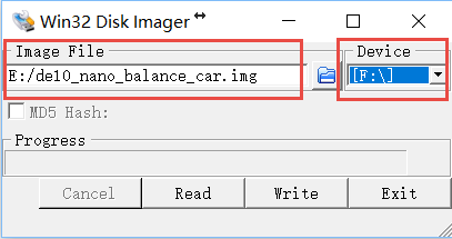
| + | *# As shown in Figure 7 -36, choose ''de10_nano_balance_car.img'' for Image File. | ||
| + | *#: | ||
| + | *#:<div style="text-align:center;"> [[Image: BAL_02_Getting_Start_Guide_pic_36.png|500px]]</div> | ||
| + | *#: | ||
| + | *#:<div style="text-align:center;"> '''Figure 7‑36 Win32DiskImager window'''</div> | ||
| + | *# Choose the drive disk of Micro SD card for Device. | ||
| + | *# Click “write” to start writing the image file to the microSD card. Wait until the image is written successfully. | ||
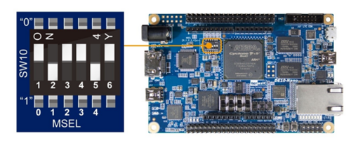
| + | *# As shown in Figure 7 -37, insert the Micro SD card into the robot. And set the mode switch(SW10) MSEL[4:0] to "01010", as shown in Figure 7 -38. | ||
| + | *#: | ||
| + | *#:<div style="text-align:center;color:#4a4a4a;">[[Image: BAL_02_Getting_Start_Guide_pic_37.png|500px]]</div> | ||
| + | *#: | ||
| + | *#:<div style="text-align:center;"> '''Figure 7‑37 Insert the Micro SD card into the robot'''</div> | ||
| + | *#: | ||
| + | *#:<div style="text-align:center;color:#4a4a4a;"> [[Image: BAL_02_Getting_Start_Guide_pic_38.png|500px]]</div> | ||
| + | *#: | ||
| + | *#:<div style="text-align:center;"> '''Figure 7‑38 Set MSEL[4:0] to "01010" for ARM Version Mode'''</div> | ||
| + | *# Power on the robot then start using it. | ||
| - | + | == 7-2 NIOS Version Restoring == | |
| - | + | ||
| - | + | ||
| - | + | ||
| - | + | ||
| + | The factory code of NIOS version is stored in the ECPS device. The following will describe how to restore factory code in the EPCS. | ||
| + | * <div style="margin-left:0.147cm;margin-right:0cm;">'''Required Equipment: '''</div> | ||
| + | *# PC: configuring the jic file to EPCS device on the robot | ||
| + | *# Mini USB Cable x 1: Connect robot to PC for configuring the file | ||
| - | |||
| - | |||
| - | |||
| - | |||
| - | |||
| + | <div style="margin-left:1.693cm;margin-right:0cm;"></div> | ||
| + | * <div style="margin-left:0.147cm;margin-right:0cm;">'''Software and file requirements:'''</div> | ||
| + | *# Ensure the Intel Quartus tools is installed properly. | ||
| + | *# The compressed .jic file for Nios version robot, it’s located at CD\Demonstration\factory\nios\ | ||
| - | |||
| - | <div style="text-align:center;"> '''Figure | + | <div style="margin-left:1.693cm;margin-right:0cm;"></div> |
| - | ** Power on the robot | + | * <div style="margin-left:0.147cm;margin-right:0cm;">'''Steps:'''</div> |
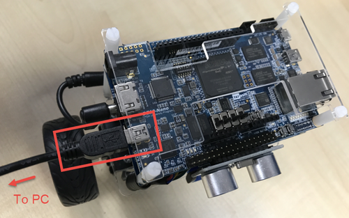
| + | *#As shown in Figure 7 -39, Connect a USB cable to the USB Blaster II connector on the robot and the PC. | ||
| + | *#:<div style="text-align:center;color:#4a4a4a;">[[Image: BAL_02_Getting_Start_Guide_pic_39.png|500px]]</div> | ||
| + | *#:<div style="text-align:center;"> '''Figure 7‑39 Connect the robot to PC via USB Mini Cable'''</div> | ||
| + | *#: | ||
| + | *#As shown in Figure 7 -40, set the mode switch (SW10) MSEL[4:0] to "10010". | ||
| + | *#:<div style="text-align:center;color:#4a4a4a;">[[Image: BAL_02_Getting_Start_Guide_pic_40.png|500px]]</div> | ||
| + | *#: | ||
| + | *#:<div style="text-align:center;"> '''Figure 7‑40 Set MSEL[4:0] to "10010" for NIOS Version Mode'''</div> | ||
| + | *#: | ||
| + | *# Copy demo_batch_jic.zip to PC and unzip it to get demo_batch_jic folder. | ||
| + | *# As shown in Figure 7 -41, input number 3 in the pop-up command window and click Enter key, it will start to configure the .jic file to EPCS device. | ||
| + | *# After the configuration is completed, remove the USB cable. Power on the robot and verify if the code is written right. | ||
| - | + | <div style="text-align:center;color:#4a4a4a;">[[Image: BAL_02_Getting_Start_Guide_pic_41.png|500px]]</div> | |
| - | + | ||
| - | <div style="text-align:center;color:#4a4a4a;"> [[Image: | + | |
| - | + | ||
| - | + | ||
| - | + | ||
| - | + | ||
| - | + | ||
| - | + | ||
| - | + | ||
| - | + | ||
| - | + | ||
| - | + | ||
| - | + | ||
| - | + | ||
| - | + | ||
| - | + | ||
| - | + | ||
| - | + | ||
| - | + | ||
| - | + | ||
| - | + | ||
| - | + | ||
| - | + | ||
| - | + | ||
| - | + | ||
| - | + | ||
| - | + | ||
| - | + | ||
| - | + | ||
| - | + | ||
| - | + | ||
| - | + | ||
| - | + | ||
| - | + | ||
| - | + | ||
| - | + | ||
| - | + | ||
| - | + | ||
| - | + | ||
| - | + | ||
| - | + | ||
| - | + | ||
| - | + | ||
<div style="text-align:center;"> '''Figure 7‑41 Command shell for write .jic file into EPCS device'''</div> | <div style="text-align:center;"> '''Figure 7‑41 Command shell for write .jic file into EPCS device'''</div> | ||
| - | + | = <span style="color:#000080;">Chpater8 Additional Information</span> = | |
| - | = | + | |
| Line 649: | Line 586: | ||
<span style="color:#000080;">'''Getting Help'''</span> | <span style="color:#000080;">'''Getting Help'''</span> | ||
| - | Here is the contact information where you can get help if you encounter problems: | + | Here is the contact information where you can get help if you encounter problems: |
| - | + | *Terasic Technologies9F, No.176, Sec.2, Gongdao 5th Rd, East Dist, Hsinchu City, Taiwan 300-70 | |
| + | *Email : [mailto:support@terasic.com support@terasic.com] | ||
| + | *Web : [http://www.terasic.com/ www.terasic.com] | ||
| Line 656: | Line 595: | ||
| - | Revision History | + | '''Revision History''' |
| - | + | {| align="left" style="border-spacing:0;width:13.781cm;" | |
| - | {| align=" | + | |
|- | |- | ||
| style="border-top:0.5pt solid #999999;border-bottom:0.5pt solid #999999;border-left:0.5pt solid #999999;border-right:none;padding:0cm;" | '''Date''' | | style="border-top:0.5pt solid #999999;border-bottom:0.5pt solid #999999;border-left:0.5pt solid #999999;border-right:none;padding:0cm;" | '''Date''' | ||
| Line 702: | Line 640: | ||
|- | |- | ||
|} | |} | ||
| - | |||
| - | |||
| - | |||
| - | |||
| - | |||
| - | |||
<div style="text-align:center;"> </div> | <div style="text-align:center;"> </div> | ||
Latest revision as of 11:36, 13 June 2018
Contents |
Chpater1 Introduction
Based on the Terasic DE10-Nano SoC board platform, designed and manufactured independently by Terasic, the Self-Balancing Robot is a Multi-functional kit. It can implement advanced features like object following, obstacle avoidance and so on. It can also be remote controlled by an Android Smartphone’s APP and IR remote control. This guide describes in detail how users can make the robot work.
1-1 Package Contents
Figure 1 -1shows the package contents of the Self-Balancing Robot kit

The Self-Balancing Robot kit package contents:
① Self-Balancing Robot
② Lithium Battery
③ Lithium Battery Charger
④ IR Remote Control
⑤ Mini USB Cable
⑥ Micro USB Cable
⑦ Quick Start Guide
Chpater2 Components and Functions
2-1 Parts and Functions
This chapter will describe the robot’s components and the functions of the components, such as the ultrasonic module, motors, wheels and driving board power interface. Figure 2 -2, Figure 2 -3, Figure 2-4 and Figure 2-5 show all the components and specify their function.

⑴ Ultrasonic module:implements obstacle avoidance.
⑵ Battery package:helps to protect the batteries and avoid bumping and damaging the battery.
⑶ Motors:drive the Self-Balancing robot wheels.
⑷ Wheels:implements the Self-Balancing robot’s movement.

⑸ Ethernet port:implements connecting to the ethernet when users develop their own designs on the Self-Balancing robot.
⑹ OTG port:implements Host or Device mode when users develop their own design on the Self-Balancing robot.
⑺ UART serial port:implement the communication between the board and PC when users develop their own design on the Self-Balancing robot.

⑻ DE10-Nano Development Board power supply jack:5V power supply port.
⑼ HDMI TX port:users can connect the Displayer to HDMI interface when they make image processing designs.
⑽ USB Blaster II port:users can download their own programs to the board through the connector.
⑾ Motor driver board power jack:connects to the battery power supply port and provides power for the Self-Balancing robot.
⑿ Main power Switch:power on or power off the Self-Balancing robot.
⒀ Battery power output plug:connect to motor driver board power port.

⒁ Battery charging jack:connects the charger to charge the battery.
⒂ Battery:the Self-Balancing robot’s power source.
2-2 DE10-Nano Kit and Motor Driver Board
The Self-Balancing Robot control system consist two boards, Terasic DE10-Nano FPGA board and Motor Driver board (BAL board) as shown in Figure 2 -6. The FPGA on the DE10-Nano is responsible for all the functions of the balance and control system. The motor driver board receives the control signal from the de10-nano to control the motor rotation. There are also some sensors and communication devices on the motor driver board. These devices can provide the status data of the robot and external communication interface to FPGA. For detailed hardware information, please refer to 03_Hardware_Manual.pdf which can be found in the CD package.

Chpater3 Setup Elements
This chapter will introduce the switches and buttons that can be set on the Self-Balancing Robot. It explains the meaning and function of the setting.
3-1 Configuration Mode Switches
The Self-Balancing Robot equips a Cyclone SoC FPGA, which means that the ARM processor is embedded in the FPGA. Therefore, there are two processor options available to control the Robot. One is to use the ARM processor and the other is implement a NIOS II processor in the FPGA. The kit provides the factory code for both processor. To switch between these two processor modes, user need to select via the mode select switch(MSEL[4:0]).
If user want to select ARM to control the robot, the MSEL[4:0] needs to switch to "01010" , as shown in Figure 3 -7. Thus, when the robot is power on, the FPGA will boot from the Micro SD card and run the Linux by ARM processor to control the robot.

When MSEL[4:0] is set to "10010", as shown in Figure 3 -8.The FPGA will boot from the configuration device(EPCS). Then, after FPGA is configured, the NIOS II processor will control the robot. For users who is beginners to learn FPGA, using NIOS II processor will be easier than deal with the ARM processor.

3-2 Operation Mode Switches
Figure 3-9 shows the SW0 and SW1 on the DE10-Nano board, Table 3-1 describes the corresponding modes and functions when SW0 and SW1 are set to different positions.

| SW[1:0] Setting | Robot mode and function | Description |
| 00 | Default mode (Bluetooth and IR mode) | The robot can be controlled by smartphone APP and IR remote control |
| 10 | Default mode and Obstacle Avoidance | The robot can be controlled by a smartphone’s APP and IR remote control, it implements the obstacle avoidance function |
| 01 | Object following and obstacle avoidance | The robot implements the object following and obstacle avoidance (In this mode, the robot will not be controlled by smartphone APP and IR remote control) |
| 11 | Debug mode | Only supports ARM version robot, the control program will stop running, users need to reboot the robot or run the program again to control the robot. Normally it is used to debug the robot. |
3-3 LEDs on the Motor Driver Board
Figure 3-10 shows the LED1 and LED2 on the motor driver board, Table 3-2 describes the functions of LED1 and LED2.

| LED name | Description |
| LED1 | Indicates the power supply status to motor driver board |
| LED2 | Indicates the motor driver board provides 5V power to the DE10-Nano board |
3-4 LEDs on DE10-Nano Board
Figure 3-11 shows the 3.3V power LED, CONF_D LED and other LEDS on the DE10-Nano board, Table 3-3 describes the LEDs functions.

| LED name | LED status | Description |
| 3.3V power LED | Light On | Power the DE10-Nano board with 3.3V from the GPIO interface |
| CONF_D | Light On | DE10-Nano board Configuration done |
| LED7 | Light On | Robot is keeping balanced status |
| LED6~5 | 0--Light On
1--Light off
| 00--robot is in default mode (Bluetooth & IR control)
01--robot is in default mode and implements obstacle avoidance function
10--robot implements object following function
|
| LED4 | Light On | Battery power supply voltage is lower than 10V |
| LED3 | Light On | Robot is turning right |
| LED2 | Light On | Robot is turning left |
| LED1 | Light On | Robot is moving backward |
| LED0 | Light On | Robot is moving forward |
Chpater4 Basic Operations
This chapter illustrates the basic operations on how to start the robot when users receive it.
4-1 Connect Power Port
Remove the red protective cap from the output plug of the battery power, as shown in Figure 4 -12.

Insert the output plug of battery power into the input port of the motor driver board, as shown in Figure 4 -13.

4-2 Power on the Robot
Place the robot on the plane, keep it in a horizontal state, then set the power switch of the motor driver board to ON position, as shown in Figure 4 -14.

4-3 Keep a Balanced State
When the LED7 on the DE10-Nano board is lit, please release the robot, it will keep balance automatically, as shown in Figure 4 -15.

4-4 Attitude Control
The robot can perform posture recognition in real time through the acceleration sensor and the gyroscope and achieve balance by controlling the motors and adjusting the posture. For example, pick up the robot, it will detect that its current state is not in a horizontal state, when the robot is placed on a horizontal plane, the robot will access its current balance status and adjust accordingly and keeping it in balanced state without any external help. If an external force causes the robot to tilt forward, the motors will quickly produce the forward motion torque to compensate for the angle of the tilt and maintain the balance of the robot. If an irregular object is placed on the robot, the robot body will maintain balance.
Chpater5 Advanced Features Demonstration
Based on the DE10-Nano SoC FPGA platform, Terasic’s Self-Balancing Robot can implement attitude algorithm, perform motion control, and execute movements autonomously, such as moving forward, turning right & left, power monitoring, object following and obstacle avoidance. Line following and obstacle avoidance are described below.
5-1 Obstacle avoidance demonstrate
Once the ultrasonic module is assembled on the robot, object following and obstacle avoidance can be implemented with the module.
When the robot is in default mode and obstacle avoidance is on (SW[1:0] is on “10” position, as shown in Table 3 -1), if the ultrasonic sensor detects the obstacle is in front of the robot and the distance is within 10 cm, the robot will stop automatically, which will implement the obstacle avoidance function, as shown in Figure 5 -16.

When the robot is in object following and obstacle avoidance mode (SW[10] is on “01” position, as shown in Table 3 -1), and if the ultrasonic sensor detects the object is in front of the robot and the distance is within 10 cm, the robot will automatically move backward to avoiding object. When an object is in front of the ultrasonic module and moves slowly and the distance is within 10 cm~20 cm, the robot will continue to move along with the object, which will implement the object following function, as shown in Figure 5 -17.

5-2 Smartphone APP Control
The robot can be remote controlled by a Smartphone APP, this section describes how to control the robot by APP .
5-2-1 Android APP Control
- Download APP
Users can download and install the Android Smartphone APP by scanning the QR code below (See Figure 5 -18) or download the APP file from the link:
http://www.terasic.com.tw/cgi-bin/page/archive.pl?Language=English&CategoryNo=238&No=1096&PartNo=4
After the installation is completed, the APP icon is shown as Figure 5 -19,


- Connect APP and Robot
Power on the robot, set SW0~3 of the DE10-Nano to Down position, as shown in Figure 5 -20.

Turn on phone Bluetooth switch, scan for available devices, normally the robot Bluetooth device name begins with “30”, as shown in Figure 5 -21.

Click the “30:...”available device to pair the robot, after they are paired successfully, the phone will show the actual name of the Bluetooth device, such as “Terasic Bal-Car 0XX”, as shown in Figure 5 -22.
Run the robot APP, click the search icon on the upper right corner of the APP GUI, as shown in Figure 5 -23.

When the actual robot device name appears, select it as the device to connect, as shown in Figure 5 -24.

After connecting to the robot successfully, it will display connection status "connected to Terasic Bal-Car 0XX" at the top left corner of the APP, as shown in Figure 5 -25.

- Control the Robot
Now users can click the yellow direction keys, STOP key and DEMO key to control the robot, Figure 5-26 shows the direction keys functions.

- Forward:robot moves forward (Ensure the ultrasonic module is installed)
- Backward:robot moves backward
- Turn left:robot turns left
- Turn right:robot turns right
- STOP:robot stops moving
- Ultrasonic On/Off: Enable/Disable ultrasonic module for obstacle avoidance function
- DEMO mode:when clicking the DEMO button, the robot will perform the scheduled action. After finishing the action, it will exit the DEMO mode automatically; if you click DEMO button again or click Stop button during DEMO mode, the robot will exit the DEMO mode automatically and keep balance where it is; if you click Forward/Backward/Left/Right button during the DEMO mode, the robot will exit the DEMO mode immediately, and perform the action according to the button
5-2-2 iOS APP Control
- Install the APP
Open the App Store on your iPhone and search for “bal_car” as shown in Figure 5 -27, then install the app:

- Connect APP and Robot
Turn on phone Bluetooth switch then run the APP, the initial APP GUI is shown as Figure 5 -28.

Power on the robot, set SW0~3 of the DE10-Nano to Down position, as shown in Figure 5 -20.
As shown in Figure 5 -28, click the refresh icon on the top right corner of the APP GUI, the APP can detect the robot Bluetooth device, it is shown as Figure 5 -29.

Click the Bluetooth device (BAL_CAR_XX), the APP will connect to the robot and shows the interactive interface for robot control, as shown in Figure 5 -30.

- Control the Robot
Now users can click the yellow direction keys, STOP key to control the robot (The latest iOS version APP hasn’t DEMO key temporary), Figure 5-31 shows all the keys functions.

- Forward:robot moves forward (Ensure the ultrasonic module is installed)
- Backward:robot moves backward
- Turn left:robot turns left
- Turn right:robot turns right
- STOP:robot stops moving
- Ultrasonic On/Off: Enable/Disable ultrasonic module for obstacle avoidance function
5-3 IR Remote Control
Figure 5 -32shows the remote control for the robot, point IR remote control to the robot, the robot will move forward when users press key 2, the robot will stop moving when user press key 5. The key 8 is used to move the robot backward, key 4 is used to turn the robot to the left, and key 6 is used to turn the robot to the right. Table 5-4 shows the functions of each key number on the controls.

| Key numbers | Function |
| 2 | Forward |
| 5 | Stop |
| 8 | Backward |
| 4 | Turn left |
| 6 | Turn right |
Chpater6 Charging the battery
The robot is powered by a three-section of lithium battery (the specific parameters of the battery can be seen outside the battery package). When the power is less than 10V, the LED4 on DE10-Nano board will light up, indicating that the battery needs to be charged in time; and the APP will also show the battery power level. If the lithium battery starts charging after it is completely drained and is completely unable to supply power to the robot, it will take up to 2 hours the battery to be fully charged. The battery charging steps are as follows:
Power off the robot, pull out the power cable, and take the battery out of the robot’s onboard battery storage space, as shown in Figure 6 -33.

As shown in Figure 6 -34, connect the charger to battery connector.

As shown in Figure 6 -35, plug the charger into the AC 220V or 110V power outlets, after the power is fully charged, the LED on the charger will light up green, then unplug the charger.

Chpater7 Restore Factory Setting
This chapter will introduce the switches and buttons that can be set on the Self-Balancing Robot. It explains the meaning and function of the setting. There are two versions of factory code: ARM and NIOS CPU-controlled version. So that, the following will describe the two methods of restoring.
7-1 ARM Version Restoring
The factory code of AMR version is stored in the Micro SD Card. The following will describe how to restore factory code in the Micro SD Card.
- Required Equipment:
- PC: Write Linux image file into SD card
- Micro SD Card: 8GB minimum
- Micro SD Card reader: Write the SD Micro SD card
- Software and file requirements:
- Win32DiskImager.zip: the tool which is used to write image file to Micro SD Card, it’s located at CD\Tool\
- de10_nano_balance_car.zip: the compressed demo image file for ARM version robot, it’s located at http://www.terasic.com.tw/cgi-bin/page/archive.pl?Language=English&No=1096&PartNo=4
- Steps:
- Copy the de10_nano_balance_car.zip to PC and unzip it to get balance_car.img file.
- Insert the Micro SD card into SD card reader and connect the card reader to PC USB port.
- Copy Win32DiskImager.zip to PC and unzip it, execute Win32DiskImager.exe in the unzipped Win32DiskImager folder.
- As shown in Figure 7 -36, choose de10_nano_balance_car.img for Image File.
- Figure 7‑36 Win32DiskImager window
- Choose the drive disk of Micro SD card for Device.
- Click “write” to start writing the image file to the microSD card. Wait until the image is written successfully.
- As shown in Figure 7 -37, insert the Micro SD card into the robot. And set the mode switch(SW10) MSEL[4:0] to "01010", as shown in Figure 7 -38.
- Figure 7‑37 Insert the Micro SD card into the robot

- Figure 7‑38 Set MSEL[4:0] to "01010" for ARM Version Mode
- Power on the robot then start using it.


7-2 NIOS Version Restoring
The factory code of NIOS version is stored in the ECPS device. The following will describe how to restore factory code in the EPCS.
- Required Equipment:
- PC: configuring the jic file to EPCS device on the robot
- Mini USB Cable x 1: Connect robot to PC for configuring the file
- Software and file requirements:
- Ensure the Intel Quartus tools is installed properly.
- The compressed .jic file for Nios version robot, it’s located at CD\Demonstration\factory\nios\
- Steps:
- As shown in Figure 7 -39, Connect a USB cable to the USB Blaster II connector on the robot and the PC.
- Figure 7‑39 Connect the robot to PC via USB Mini Cable
- As shown in Figure 7 -40, set the mode switch (SW10) MSEL[4:0] to "10010".
- Figure 7‑40 Set MSEL[4:0] to "10010" for NIOS Version Mode
- Copy demo_batch_jic.zip to PC and unzip it to get demo_batch_jic folder.
- As shown in Figure 7 -41, input number 3 in the pop-up command window and click Enter key, it will start to configure the .jic file to EPCS device.
- After the configuration is completed, remove the USB cable. Power on the robot and verify if the code is written right.
- As shown in Figure 7 -39, Connect a USB cable to the USB Blaster II connector on the robot and the PC.


Chpater8 Additional Information
Getting Help
Here is the contact information where you can get help if you encounter problems:
- Terasic Technologies9F, No.176, Sec.2, Gongdao 5th Rd, East Dist, Hsinchu City, Taiwan 300-70
- Email : support@terasic.com
- Web : www.terasic.com
Revision History
| Date | Version | Changes |
| 2018.03.16 | First publication | |