HERO Doucment Hardware Manual Chinese
From Terasic Wiki
(→Chapter 1 介绍) |
|||
| Line 48: | Line 48: | ||
::*温度感应器 | ::*温度感应器 | ||
::*电源监测 | ::*电源监测 | ||
| + | |||
| + | =Chapter 2 System Interface Introduction and Description= | ||
| + | |||
| + | ==2.1. Overview== | ||
| + | |||
| + | The HERO platform is composed of CPU host system and FPGA accelerator card. As shown in figure 2-1, external interfaces on the HERO platform are also divided into two categories. The peripheral interfaces marked in orange line are CPU host system interface, such as HDMI and USB interfaces. With the two interfaces, operating system running on the CPU host system can use mouse or screen output function. | ||
| + | |||
| + | The peripheral interfaces marked in blue line are FPGA accelerator card interface. With these interfaces, FPGA acceleration card can have the ability to expand peripherals. For example, connecting to ethernet the FPGA acceleration card can have communication ability to deal with network function. But these interfaces require users to implement corresponding design in FPGA. The default code doesn’t include these designs. | ||
| + | |||
| + | In addition, it should be noted that these two systems are independent, for example, the Ethernet is connected to the FPGA acceleration card, then, the FPGA acceleration card can have network ability but the CPU host system can’t. Similarly, plug the USB mouse on the FPGA acceleration card, the FPGA acceleration card can detect the mouse, the CPU host system can’t. | ||
| + | |||
| + | [[File:Main_Interfaces_on_HERO_platform.jpg|600px]] | ||
| + | |||
| + | '''Figure 2-1 The Main Interfaces on HERO platform''' | ||
| + | |||
| + | |||
| + | Next, we will introduce the power supply on HERO platform and the interface of CPU host system. The FPGA accelerator card interfaces will be described in Chapter 3. | ||
| + | |||
| + | ==2.2 12V System Power Input and FPGA Power Switch== | ||
| + | |||
| + | Figure 2-2 shows the power input port of HERO platform and FPGA power switch. DC 12V power supplier is required to supply the power.The FPGA power switch is the FPGA accelerator card power switch. Please start this switch first to powered and configured the FPGA, and later, power on the CPU system, then, the CPU system can detect the FPGA accelerator card device. | ||
| + | |||
| + | [[File:Hero_CPU_host_system_Power_button.jpg|600px]] | ||
| + | |||
| + | '''Figure 2-2 12V System Power Input and FPGA Power Switch''' | ||
| + | |||
| + | ==2.3 CPU host system Power button== | ||
| + | |||
| + | Figure 2-3 is the power button of the CPU host system, and this button can be pressed to turn on the CPU host system. As in the most PC machines, when the CPU host system is turned on (blue light will appear on the button), pressing this button for four seconds will force the system power to shut down. And press one time, the operation system will appear restart options. | ||
| + | |||
| + | [[File:Hero_CPU_host_system_interface.jpg|600px]] | ||
| + | |||
| + | '''Figure 2-3 CPU host system Power button''' | ||
| + | |||
| + | ==2.4 CPU host system interface== | ||
| + | |||
| + | This section describes the peripheral interfaces of the CPU host system. | ||
| + | |||
| + | ===High Definition Multimedia Interface* (HDMI*)=== | ||
| + | |||
| + | |||
| + | [[File:Hero_High_Definition_Multimedia_Interface.jpg|600px]] | ||
| + | |||
| + | '''Figure 2-4 High Definition Multimedia Interface''' | ||
| + | |||
| + | The HDMI port supports standard, enhanced, or high definition video, plus multi-channel digital audio on a single cable. The port is compatible with all ATSC and DVB HDTV standards and supports eight full range channels at 24-bit/96 kHz audio of lossless audio formats. The maximum supported resolution is 4096 x 2160 @ 60 Hz, 24bpp. The HDMI port is compliant with the HDMI 2.0 specification. | ||
| + | |||
| + | ===Gigabit Ethernet LAN Port=== | ||
| + | |||
| + | [[File:Hero_CPU_Gigabit_Ethernet_LAN_Port.jpg|600px]] | ||
| + | |||
| + | '''Figure 2-4 Gigabit Ethernet LAN Port''' | ||
| + | |||
| + | The Ethernet Port on the CPU host system supports the following features: | ||
| + | • Compliant with the 1 Gb/s Ethernet 802.3, 802.3u, 802.3z, 802.3ab specifications | ||
| + | • Multi-speed operation: 10/100/1000 Mb/s | ||
| + | • Full-duplex operation at 10/100/1000 Mb/s; Half-duplex operation at 10/100 Mb/s | ||
| + | • Flow control support compliant with the 802.3X specification as well as the specific operation of symmetrical flow control defined by 802.3z | ||
| + | • VLAN support compliant with the 802.3q specification | ||
| + | |||
| + | Two LEDs are built into the RJ-45 LAN connector (shown in Figure 2-5). | ||
| + | |||
| + | [[File:Hero_CPU_RJ-45_LAN_connector_LED.jpg|600px]] | ||
| + | |||
| + | '''Figure 2-5 Two LEDs on RJ-45 LAN connector''' | ||
| + | |||
| + | Table 2-1 describes the LED states when the board is powered up and the LAN subsystem is operating. | ||
| + | |||
| + | '''Table 2-1''' | ||
| + | :{| class="wikitable" | ||
| + | |- | ||
| + | !LED !!LED Color !!LED State !!Condition | ||
| + | |- | ||
| + | |rowspan="3"|Link || rowspan="3"|Green || OFF ||LAN link is not established | ||
| + | |- | ||
| + | |On ||LAN link is established | ||
| + | |- | ||
| + | |Blinking ||LAN activity is accurring | ||
| + | |- | ||
| + | |rowspan="3"|Data Rate || rowspan="3"|Green/Yellow || Off ||10Mb/s data rate is selected | ||
| + | |- | ||
| + | |Green ||100Mb/s data rate is selected | ||
| + | |- | ||
| + | |Yellow ||1000Mb/s data rate is selected | ||
| + | |} | ||
| + | |||
| + | ===USB 3.0 Ports=== | ||
| + | The CPU system of HERO platform provides two USB 3.0 ports, as shown in figure below. The maximum current for each port is 900 mA. | ||
| + | :[[File:Hero USB 3.0 Ports.jpg|500px]] | ||
| + | :::::'''Figure 2-6 Hero USB 3.0 Ports''' | ||
| + | |||
| + | ===USB Type-C connector=== | ||
| + | The port supports Thunderbolt™ 3 with up to 40Gbps of data throughput, one 4k (60Hz) monitor output, USB3.1 (Gen 2) connection and charging capabilities up to 5V at 3A. <br/> | ||
| + | It also supports DisplayPort 1.2 specification for display connections between consumer electronics devices such as high definition optical disc players, set top boxes, and TV displays. The maximum supported resolution is 4096 x 2304 @ 60 Hz, 24bpp. | ||
| + | :[[File:Hero USB Type-C Connector.jpg|500px]] | ||
| + | :::::'''Figure 2-7 Hero USB Type-C Connector''' | ||
Revision as of 09:43, 29 September 2018
Contents |
第一章 介绍
1.1 概述
HERO平台全称为Heterogeneous Extensible Robot Open Platform,是专为智能机器人(包括服务机器人、医疗机器人、自动驾驶汽车等)打造的一套低功耗、高性能、体积小的异构系统平台方案。在此方案中,CPU作为控制中心,与FPGA和其他专用加速器芯片(如Movidius的VPU)搭配,能够提供高效的性能。整套HERO硬件系统采用了英特尔酷睿?系列CPU,搭载英特尔Arria 10 GX系列1150型FPGA作为异构加速器。
传统的FPGA编程方式令多数软件工程师望而却步,而HERO平台为大家带来了福音。除了传统的专业编程模型,HERO平台专门定制的BSP(Board Support Package)还支持基于OpenCL的flow开发,给广大的算法和软件工程师提供了友好的编程接口。为了支持OpenCL Flow,HERO平台上移植了完整的FPGA板级支持包(Board Support Package),作为HERO SDK的一个组成部分提供给用户。现有HERO SDK BSP的FPGA逻辑部分主要包括高速通信接口PCIe IP核、内存DMA控制器、片外高速内存DDR4接口,以及和FPGA内部模块之间的通信接口。如果用户想增加FPGA与外部接口之间的通讯, HERO平台也有相应的BSP参考设计,能够指导客户更好、更快地实现各种灵活多变的外部接口。
HERO平台的应用前景广阔。以服务机器人为例,其主要作用是帮助人完成任务和动作。为了实现这一目标,研发人员需要在机器人上实现各种复杂的应用控制技术,包括视觉、定位、运动、抓取等。FPGA可以在这些关键应用上发挥极大的价值,让复杂算法的处理变得高效而实时,带给用户良好的体验。
1.2 技术规格
Hero平台有两个板卡组合而成,分别为 CPU 主机系统与 FPGA加速度系统(见图1-1)。两者以PCIe接口连接进行传输与通信, 完成CPU协同FPGA的各种计算加速、算法实现功能。FPGA系统使用Intel Arria10 FPGA PCIe板卡。下面将介绍这两大主板系统的各个参数规格:
- CPU主系统
- 处理器: 英特尔® 酷睿™ i5-7260U/i7-7567U(根据客户订单需求而定)
- 内存: DDR4-2133 1.2V SO-DIMM 8GB
- 硬盘: Sata SSD 256G
- 显卡
- 集成显卡
- 图像输出: HDMI 2.0a;USB-C (DP1.2)
- 外围接口
- USB Type C端口 x1
- Thunderbolt™ 3 (40Gbps)
- USB 3.1 Gen 2 (10Gbps)
- DisplayPort (DP 1.2)
- USB 3.0/2.0 端口x2
- 局域网: Gigabit (10/100/1000 Mb/s)局域网
- 无线: 英特尔® Wireless-AC 8265 + 蓝牙4.2
- FPGA加速系统
- FPGA: Altera Arria 10 GX FPGA (10AX115S2F45I1SG)
- FPGA配置电路
- 板载USB Blaster II或FPGA编程的JTAG接头
- 快速被动并行配置(FPPx32):通过MAX II CPLD和闪存
- 内存
- 256MB闪存
- 2GB DDR44 -2400 x 64bit
- 通信与扩展
- PCI Express (PCIe) x8 edge接头
- USB 3.0 Host/Device
- 以太网
- UART/CAN/SPI/I2C
- 通用用户输入/输出:
- 8 LEDs
- 3 Push-buttons
- 8 DIP Switch
- 时钟
- 50/100/125MHz固定时钟
- 可编程PLL
- 系统监测与控制
- 温度感应器
- 电源监测
Chapter 2 System Interface Introduction and Description
2.1. Overview
The HERO platform is composed of CPU host system and FPGA accelerator card. As shown in figure 2-1, external interfaces on the HERO platform are also divided into two categories. The peripheral interfaces marked in orange line are CPU host system interface, such as HDMI and USB interfaces. With the two interfaces, operating system running on the CPU host system can use mouse or screen output function.
The peripheral interfaces marked in blue line are FPGA accelerator card interface. With these interfaces, FPGA acceleration card can have the ability to expand peripherals. For example, connecting to ethernet the FPGA acceleration card can have communication ability to deal with network function. But these interfaces require users to implement corresponding design in FPGA. The default code doesn’t include these designs.
In addition, it should be noted that these two systems are independent, for example, the Ethernet is connected to the FPGA acceleration card, then, the FPGA acceleration card can have network ability but the CPU host system can’t. Similarly, plug the USB mouse on the FPGA acceleration card, the FPGA acceleration card can detect the mouse, the CPU host system can’t.

Figure 2-1 The Main Interfaces on HERO platform
Next, we will introduce the power supply on HERO platform and the interface of CPU host system. The FPGA accelerator card interfaces will be described in Chapter 3.
2.2 12V System Power Input and FPGA Power Switch
Figure 2-2 shows the power input port of HERO platform and FPGA power switch. DC 12V power supplier is required to supply the power.The FPGA power switch is the FPGA accelerator card power switch. Please start this switch first to powered and configured the FPGA, and later, power on the CPU system, then, the CPU system can detect the FPGA accelerator card device.

Figure 2-2 12V System Power Input and FPGA Power Switch
2.3 CPU host system Power button
Figure 2-3 is the power button of the CPU host system, and this button can be pressed to turn on the CPU host system. As in the most PC machines, when the CPU host system is turned on (blue light will appear on the button), pressing this button for four seconds will force the system power to shut down. And press one time, the operation system will appear restart options.

Figure 2-3 CPU host system Power button
2.4 CPU host system interface
This section describes the peripheral interfaces of the CPU host system.
High Definition Multimedia Interface* (HDMI*)

Figure 2-4 High Definition Multimedia Interface
The HDMI port supports standard, enhanced, or high definition video, plus multi-channel digital audio on a single cable. The port is compatible with all ATSC and DVB HDTV standards and supports eight full range channels at 24-bit/96 kHz audio of lossless audio formats. The maximum supported resolution is 4096 x 2160 @ 60 Hz, 24bpp. The HDMI port is compliant with the HDMI 2.0 specification.
Gigabit Ethernet LAN Port

Figure 2-4 Gigabit Ethernet LAN Port
The Ethernet Port on the CPU host system supports the following features: • Compliant with the 1 Gb/s Ethernet 802.3, 802.3u, 802.3z, 802.3ab specifications • Multi-speed operation: 10/100/1000 Mb/s • Full-duplex operation at 10/100/1000 Mb/s; Half-duplex operation at 10/100 Mb/s • Flow control support compliant with the 802.3X specification as well as the specific operation of symmetrical flow control defined by 802.3z • VLAN support compliant with the 802.3q specification
Two LEDs are built into the RJ-45 LAN connector (shown in Figure 2-5).

Figure 2-5 Two LEDs on RJ-45 LAN connector
Table 2-1 describes the LED states when the board is powered up and the LAN subsystem is operating.
Table 2-1
LED LED Color LED State Condition Link Green OFF LAN link is not established On LAN link is established Blinking LAN activity is accurring Data Rate Green/Yellow Off 10Mb/s data rate is selected Green 100Mb/s data rate is selected Yellow 1000Mb/s data rate is selected
USB 3.0 Ports
The CPU system of HERO platform provides two USB 3.0 ports, as shown in figure below. The maximum current for each port is 900 mA.
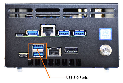
- Figure 2-6 Hero USB 3.0 Ports

USB Type-C connector
The port supports Thunderbolt™ 3 with up to 40Gbps of data throughput, one 4k (60Hz) monitor output, USB3.1 (Gen 2) connection and charging capabilities up to 5V at 3A.
It also supports DisplayPort 1.2 specification for display connections between consumer electronics devices such as high definition optical disc players, set top boxes, and TV displays. The maximum supported resolution is 4096 x 2304 @ 60 Hz, 24bpp.
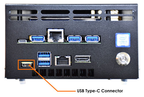
- Figure 2-7 Hero USB Type-C Connector
