Terasic USB Blaster III Manual
From Terasic Wiki
(→Supported Devices and Host System) |
(→USB Blaster Self Test) |
||
| (111 intermediate revisions not shown) | |||
| Line 4: | Line 4: | ||
The UBT3 connects the Host and the FPGA on the user's board through the USB Port and 10-Pin cable. At the same time, it can support several target board voltage standards, allowing UBT3 to be widely used in various FPGA boards. | The UBT3 connects the Host and the FPGA on the user's board through the USB Port and 10-Pin cable. At the same time, it can support several target board voltage standards, allowing UBT3 to be widely used in various FPGA boards. | ||
| - | = Supported Devices | + | = Supported Devices, Host System and Software = |
| - | The | + | The Altera FPGAs, serial configuration device, host systems and Quartus Prime software that UBT3 supported are list in Table 1-1, Table 1-2, Table 1-3 and Table 1-4. |
| - | <div style=""> '''Table 1‑1 Supported | + | <div style=""> '''Table 1‑1 Supported Altera FPGA Devices'''</div> |
{| class="" border="1" | {| class="" border="1" | ||
|- bgcolor=#00A9FF | |- bgcolor=#00A9FF | ||
| - | !FPGA | + | !FPGA Series |
| - | ! | + | !Deivces |
|- | |- | ||
| - | ||''' | + | ||'''Agilex''' |
| - | || | + | ||Agilex 3, Agilex 5, Agilex 7, Agilex 9 |
|- | |- | ||
| - | ||'''Stratix''' | + | ||'''Stratix''' |
| - | ||Stratix 10, Stratix V, Stratix IV, Stratix III | + | ||Stratix 10, Stratix V, Stratix IV, Stratix III |
|- | |- | ||
| - | ||'''Arria''' | + | ||'''Arria''' |
| - | ||Arria 10, Arria V | + | ||Arria 10, Arria V |
|- | |- | ||
|- | |- | ||
| - | ||'''Cyclone''' | + | ||'''Cyclone''' |
| - | ||Cyclone 10,Cyclone V, Cyclone IV, Cyclone III, Cyclone II | + | ||Cyclone 10 GX, Cyclone 10 LP, Cyclone 10,Cyclone V, Cyclone IV, Cyclone III, Cyclone II |
|- | |- | ||
|- | |- | ||
| - | ||'''MAX''' | + | ||'''MAX''' |
| - | || | + | ||MAX 10, MAX V, MAX II |
| - | + | ||
| - | + | ||
| - | + | ||
| - | + | ||
|- | |- | ||
|} | |} | ||
| Line 44: | Line 40: | ||
{| class="" border="1" | {| class="" border="1" | ||
|- bgcolor=#00A9FF | |- bgcolor=#00A9FF | ||
| - | ! | + | !Serial Flash Series |
| + | |- | ||
| + | ||EPCQA devices | ||
| + | |- | ||
| + | |- | ||
| + | ||Micron MT25QL devices | ||
| + | |- | ||
| + | |- | ||
| + | ||Micron MT25QU devices | ||
| + | |- | ||
| + | |- | ||
| + | ||Macronix MX25L devices | ||
| + | |- | ||
| + | |- | ||
| + | ||Macronix MX25U devices | ||
| + | |- | ||
|- | |- | ||
| - | || | + | ||Macronix MX66U devices |
|- | |- | ||
| - | |||
|- | |- | ||
| - | || | + | ||Infineon S25FL devices |
|- | |- | ||
|} | |} | ||
| Line 62: | Line 72: | ||
!Host System | !Host System | ||
|- | |- | ||
| - | ||Window | + | ||Window 10/11 (64-bit) |
|- | |- | ||
||Linux | ||Linux | ||
| + | |- | ||
| + | |} | ||
| + | |||
| + | |||
| + | <div style=""> '''Table 1‑4 Supported Quartus software'''</div> | ||
| + | |||
| + | {| class="" border="1" | ||
| + | |- bgcolor=#00A9FF | ||
| + | !Quartus software | ||
| + | |- | ||
| + | ||Quartus® Prime version 25.1 or later | ||
|- | |- | ||
|} | |} | ||
| Line 70: | Line 91: | ||
= Operating Conditions = | = Operating Conditions = | ||
| - | + | UBT3 supports several voltage standard of the target board. Table 1-5 shows the supported voltage. | |
| - | Users need to pay attention to whether the JTAG voltage standard of the target board is within the range of Table 1- | + | Users need to pay attention to whether the JTAG voltage standard of the target board is within the range of Table 1-5. |
| - | <div style=""> '''Table | + | <div style=""> '''Table 1‑5 Supported Target Board Supply Voltage'''</div> |
{| class="" border="1" | {| class="" border="1" | ||
|- bgcolor=#00A9FF | |- bgcolor=#00A9FF | ||
| - | ! | + | !Supported Target Board Supply Voltage |
|- | |- | ||
| - | ||1.2V | + | ||1.2V |
|- | |- | ||
| - | ||1.5V | + | ||1.5V |
|- | |- | ||
| - | ||1.8V | + | ||1.8V |
|- | |- | ||
||2.5V | ||2.5V | ||
| Line 91: | Line 112: | ||
|} | |} | ||
| - | + | =Pin Define= | |
| + | The following picture and Table 1-6 list the pins of the Terasic UBT3 Download Cable female plug and | ||
| + | describe their functions in the JTAG and Active Serial modes. | ||
| - | + | [[File:Ubt3 pin define.png|200px]] | |
| - | + | ||
| - | + | ||
| - | + | ||
| - | + | ||
| - | [[File: | + | |
| + | <div style=""> '''Table 1-6 Pin Number and Description'''</div> | ||
{| class="" border="1" | {| class="" border="1" | ||
| Line 105: | Line 124: | ||
!Pin Number | !Pin Number | ||
!Pin Define | !Pin Define | ||
| - | !JTAG Mode | + | !JTAG Mode Description |
| - | ! | + | !AS Mode Description |
|- | |- | ||
||1 | ||1 | ||
| - | || | + | ||TCK |
||Clock signal | ||Clock signal | ||
||Clock signal | ||Clock signal | ||
| Line 119: | Line 138: | ||
|- | |- | ||
||3 | ||3 | ||
| - | || | + | ||TDO |
| - | || | + | ||Test data output |
||Configuration done | ||Configuration done | ||
|- | |- | ||
||4 | ||4 | ||
||TRGVCC | ||TRGVCC | ||
| - | ||Target power | + | ||Target power supply |
| - | ||Target power | + | ||Target power supply |
|- | |- | ||
||5 | ||5 | ||
| - | || | + | ||TMS |
| - | || | + | ||Test mode select input |
| - | ||Configuration control | + | ||Configuration control |
|- | |- | ||
||6 | ||6 | ||
| - | || | + | ||PROC_RST |
| - | || | + | ||Processor reset |
| - | || | + | ||Target chip enable |
|- | |- | ||
||7 | ||7 | ||
| - | |||
||- | ||- | ||
| - | || | + | ||- |
| + | ||- | ||
|- | |- | ||
||8 | ||8 | ||
| - | || | + | ||TRST |
| - | || | + | ||Test reset |
||Serial configuration device chip select | ||Serial configuration device chip select | ||
|- | |- | ||
||9 | ||9 | ||
| - | || | + | ||TDI |
| - | || | + | ||Test data input |
| - | ||Active serial data | + | ||Active serial data input |
|- | |- | ||
||10 | ||10 | ||
| Line 159: | Line 178: | ||
|} | |} | ||
| - | = | + | =LED Description= |
| + | The LED on the Terasic USB Blaster III download cable indicates different conditions as listed in Table 1-7. | ||
| - | + | <div style=""> '''Table 1-7 LED Indicator'''</div> | |
| - | = | + | {| class="" border="1" |
| + | |- bgcolor=#00A9FF | ||
| + | !LED Color | ||
| + | !State | ||
| + | !Description | ||
| + | |- | ||
| + | ||None | ||
| + | ||Off | ||
| + | ||Not connected or is suspended | ||
| + | |- | ||
| + | ||Blue | ||
| + | ||Solid | ||
| + | ||Connected, not in use | ||
| + | |- | ||
| + | ||Green | ||
| + | ||Solid | ||
| + | ||JTAG port open, idle | ||
| + | |- | ||
| + | ||Green | ||
| + | ||Blinking | ||
| + | ||JTAG port open, active | ||
| + | |- | ||
| + | ||Purple | ||
| + | ||Blinking | ||
| + | ||Occurs when JTAG command Identify(1) is triggered | ||
| + | |- | ||
| + | |} | ||
| - | + | (1) jtagconfig --setparam <cable number> Identify <1=on, 0=off> | |
| - | + | ||
| - | + | =Dimension of the Terasic USB Blaster III Download Cable = | |
| - | the Terasic Download Cable | + | |
| - | + | ||
| - | + | ||
| + | [[File:Ubt3 dimension.png|600px]] | ||
| - | + | =Using the Terasic USB Blaster III Download Cable= | |
| - | + | To start using the USB Blaster III Download Cable, user need to install the drivers on your | |
| + | system and set up the hardware in the Altera Quartus® Prime software. | ||
| - | + | To program or configure the device, connect the host system to the device board using | |
| + | the Terasic USB Blaster III Download Cable and initiate the programming or configuration using | ||
| + | the Altera Quartus Prime Programmer. You can also use the cable with the Quartus | ||
| + | Prime Signal Tap Logic Analyzer for logic analysis. It also can be used with JTAG and debug tools supported by the JTAG server such as System Console, Nios® V debugger. | ||
| - | + | *'''Install the driver for Windows''' | |
| - | + | When installing Quartus Prime software,ensure the following options are selected: | |
| + | :*Install USB Blaster III driver | ||
| + | :*Install USB Blaster III driver (Requires UART FTDI driver) | ||
| + | :*Install JTAG server as a Windows service and run automatically when Windows starts | ||
| - | + | [[File:Install USB BlasterIII driver.png|600px]] | |
| - | + | *'''Install the driver for Linux''' | |
| - | + | ||
| - | + | ||
| - | + | ||
| - | + | ||
| - | + | ||
| - | + | ||
| - | + | ||
| - | + | ||
| - | + | ||
| - | + | ||
| - | + | [https://www.terasic.com.tw/wiki/Altera_USB_Blaster_III_Driver_Installation_Instructions Altera_USB_Blaster_III_Driver_Installation_Instructions] | |
| - | + | =Changing TCK Frequency of the Terasic USB Blaster III Download Cable= | |
| + | The Terasic USB Blaster III download able has a default TCK frequency of 15 MHz but can be run at 30 MHz if signal integrity and board timing requirements are met. | ||
| - | + | To change the TCK frequency of the Terasic USB Blaster III download cable, users can use Quartus Prime Programmer and Command Line. | |
| - | + | *'''Changing TCK Frequency with Quartus Prime Programmer''' | |
| + | #In Quartus Prime Programmer, click on '''Hardware Setup'''. | ||
| + | #Under the '''Hardware Settings''' tab, uncheck '''Auto-adjust frequency at chain scanning''' to disable the feature. | ||
| + | #Type in one of the recommended frequencies in the '''Hardware frequency''' field. | ||
| + | #Close the '''Hardware Setup''' dialog box to save the settings. | ||
| + | :[[File:Programmer TCK.png|550px]] | ||
| + | *'''TCK Frequency Auto-Adjust with Quartus Prime Programmer''' | ||
| + | A checkbox is added in the Quartus Prime Programmer's Hardware Setup dialog box to toggle the auto-adjust frequency feature on and off. When the auto-adjust frequency is enabled, the new adjusted TCK frequency value is shown under the message box of the Programmer GUI. | ||
| + | This checkbox is grayed out when the auto-adjust frequency feature is unavailable. | ||
| + | [[File:Programmer TCK Auto.png|550px]] | ||
| - | ''' | + | *'''Changing TCK Frequency with Command Line Programming''' |
| + | To change the TCK frequency of the Terasic USB Blaster III download cable with command line programming: | ||
| + | #Open the command line interface with the UBT3 bin directory in your path. Example: '''''E:\altera_pro\25.1.1\quartus\bin64''''' | ||
| + | #Enter the following command to change the TCK frequency: '''''jtagconfig --setparam <cable_number> JtagClock <frequency><unit_prefix>'''''. | ||
| + | ::'''''cable_number''''' is the UBT3 download able to be modified. | ||
| + | ::'''''frequency''''' is the desired TCK frequency, it supports 30M,15M,10M,7500K,6M,5M,3M,2M,1M and <30/n>M (between 10kHz and 6MHz, where n represents an integer value number). | ||
| + | ::'''''unit_prefix''''' is the unit prefix for the frequency (for example, M for MHz) | ||
| + | An example for setting TCK frequency to 6 MHz: '''''jtagconfig --setparam 1 JtagClock 6M''''' | ||
| - | + | [[File:TCK 6M.png|550px]] | |
| + | *'''TCK Frequency Auto-Adjust with Command Line Programming''' | ||
| + | It is turned on by default and can be toggled on and off via either the command line interface. The feature resets to default when the cable is reconnected or the JTAG server is restarted. | ||
| + | #To turn off the auto-adjust frequency feature, use the following command: '''''jtagconfig --setparam <cable number> JtagClockAutoAdjust 0''''' | ||
| + | #To turn on the auto-adjust frequency feature, use the following command: '''''jtagconfig --setparam <cable number> JtagClockAutoAdjust 1''''' | ||
| + | #You may use the following command to check whether the auto-adjust frequency is enabled. The expected output is 0 if autoadjust is disabled and 1 if the auto-adjust is enabled: '''''Jtagconfig --getparam <cable number> JtagClockAutoAdjust''''' | ||
| - | + | =USB Blaster Self Test= | |
| - | + | This section describes users how to test whether the on-board USB blaster III or USB blaster III cable is properly installed and operated. | |
| - | + | #<font size="2"><font face="Arial">Power on the FPGA board and connect USB blaster III port or USB blaster III cable to PC.</font></font> <br/><font size="2"><font face="Arial">Check if there is '''JTAG cables''' in the Windows '''Device Manager''' has an '''USB Blaster III'''.</font></font><br/><font size="2"><font face="Arial">If yes, users can use Quartus programmer and download FPGA code.</font></font><br/>[[File:Altera USB BlasterIII.png]]<br/><br/> | |
| + | #<font size="2"><font face="Arial">If USB Blaster III isn’t showed, please check whether the '''Other devices''' has '''Unknown device'''.</font></font><br/><font size="2"><font face="Arial">If yes, please refer to the steps described in this link:[https://www.terasic.com.tw/wiki/Altera_USB_Blaster_II_Driver_Installation_Instructions Altera USB Blaster II Driver Installation Instructions] to install the USB blaster III driver. The installation steps are generic, you just need to select the USB Blaster III driver located in the Quartus installation directory.</font></font><br/>[[File:Device Manger2.png]].<br/><br/> | ||
| + | #<font size="2"><font face="Arial">If no '''Unknown device''':</font></font> | ||
| + | ::<font size="2"><font face="Arial">i.Make sure the board power is on and the port on board which connected to PC is USB blaster III port.</font></font> | ||
| + | ::<font size="2"><font face="Arial">ii.If step i is OK:</font></font> | ||
| + | :::<font size="2"><font face="Arial">a.Test with another PC to see if the OS can detect unknown device.</font></font> | ||
| + | :::<font size="2"><font face="Arial">b.Test with another USB blaster III cable.</font></font><br/>[[File:USB BlasterIII cable.png|200px]]<br/> | ||
| + | :::<font size="2"><font face="Arial">c.If still with the same problem, please contact our technical support team via '''support@terasic.com''' and provide below information:</font></font> | ||
| + | ::::*<font size="2"><font face="Arial">PC OS version: Win10-64bit, Win11-64bit or Linux-64bit.</font></font> | ||
| + | ::::*<font size="2"><font face="Arial">Whether you tested follow the above processes.</font></font> | ||
| + | ::::*<font size="2"><font face="Arial">The Quartus version you installed: Quartus Prime 25.1 or others.</font></font> | ||
| + | = FAQ = | ||
| + | '''1. Q: What is the operating temperature specification of the UBT3? | ||
| - | + | '''A:'''The UBT3 is designed to operate in the industrial temperature range (-40°C to +85°C). | |
| - | + | ||
| - | '''A:'''The | + | |
| - | + | ||
| - | + | ||
| - | + | ||
| - | + | ||
| - | + | ||
| - | + | ||
| - | + | ||
| - | + | ||
| - | + | ||
| - | + | ||
| - | + | ||
| - | + | ||
| - | + | ||
| - | + | ||
| - | + | ||
| - | + | ||
| - | + | ||
| - | + | ||
| - | + | ||
| - | + | ||
| - | + | ||
| - | + | ||
| - | + | ||
Latest revision as of 14:38, 31 August 2026
Introduction
The main function of the Terasic USB Blaster III Download Cable (UBT3) is to allow users to download configuration data to the system during prototype development, or to program data into the system during production. The UBT3 connects the Host and the FPGA on the user's board through the USB Port and 10-Pin cable. At the same time, it can support several target board voltage standards, allowing UBT3 to be widely used in various FPGA boards.
Supported Devices, Host System and Software
The Altera FPGAs, serial configuration device, host systems and Quartus Prime software that UBT3 supported are list in Table 1-1, Table 1-2, Table 1-3 and Table 1-4.
| FPGA Series | Deivces |
|---|---|
| Agilex | Agilex 3, Agilex 5, Agilex 7, Agilex 9 |
| Stratix | Stratix 10, Stratix V, Stratix IV, Stratix III |
| Arria | Arria 10, Arria V |
| Cyclone | Cyclone 10 GX, Cyclone 10 LP, Cyclone 10,Cyclone V, Cyclone IV, Cyclone III, Cyclone II |
| MAX | MAX 10, MAX V, MAX II |
| Serial Flash Series |
|---|
| EPCQA devices |
| Micron MT25QL devices |
| Micron MT25QU devices |
| Macronix MX25L devices |
| Macronix MX25U devices |
| Macronix MX66U devices |
| Infineon S25FL devices |
| Host System |
|---|
| Window 10/11 (64-bit) |
| Linux |
| Quartus software |
|---|
| Quartus® Prime version 25.1 or later |
Operating Conditions
UBT3 supports several voltage standard of the target board. Table 1-5 shows the supported voltage. Users need to pay attention to whether the JTAG voltage standard of the target board is within the range of Table 1-5.
| Supported Target Board Supply Voltage |
|---|
| 1.2V |
| 1.5V |
| 1.8V |
| 2.5V |
| 3.3V |
Pin Define
The following picture and Table 1-6 list the pins of the Terasic UBT3 Download Cable female plug and describe their functions in the JTAG and Active Serial modes.

| Pin Number | Pin Define | JTAG Mode Description | AS Mode Description |
|---|---|---|---|
| 1 | TCK | Clock signal | Clock signal |
| 2 | GND | Signal ground | Signal ground |
| 3 | TDO | Test data output | Configuration done |
| 4 | TRGVCC | Target power supply | Target power supply |
| 5 | TMS | Test mode select input | Configuration control |
| 6 | PROC_RST | Processor reset | Target chip enable |
| 7 | - | - | - |
| 8 | TRST | Test reset | Serial configuration device chip select |
| 9 | TDI | Test data input | Active serial data input |
| 10 | GND | Signal ground. | Signal ground |
LED Description
The LED on the Terasic USB Blaster III download cable indicates different conditions as listed in Table 1-7.
| LED Color | State | Description |
|---|---|---|
| None | Off | Not connected or is suspended |
| Blue | Solid | Connected, not in use |
| Green | Solid | JTAG port open, idle |
| Green | Blinking | JTAG port open, active |
| Purple | Blinking | Occurs when JTAG command Identify(1) is triggered |
(1) jtagconfig --setparam <cable number> Identify <1=on, 0=off>
Dimension of the Terasic USB Blaster III Download Cable

Using the Terasic USB Blaster III Download Cable
To start using the USB Blaster III Download Cable, user need to install the drivers on your system and set up the hardware in the Altera Quartus® Prime software.
To program or configure the device, connect the host system to the device board using the Terasic USB Blaster III Download Cable and initiate the programming or configuration using the Altera Quartus Prime Programmer. You can also use the cable with the Quartus Prime Signal Tap Logic Analyzer for logic analysis. It also can be used with JTAG and debug tools supported by the JTAG server such as System Console, Nios® V debugger.
- Install the driver for Windows
When installing Quartus Prime software,ensure the following options are selected:
- Install USB Blaster III driver
- Install USB Blaster III driver (Requires UART FTDI driver)
- Install JTAG server as a Windows service and run automatically when Windows starts

- Install the driver for Linux
Altera_USB_Blaster_III_Driver_Installation_Instructions
Changing TCK Frequency of the Terasic USB Blaster III Download Cable
The Terasic USB Blaster III download able has a default TCK frequency of 15 MHz but can be run at 30 MHz if signal integrity and board timing requirements are met.
To change the TCK frequency of the Terasic USB Blaster III download cable, users can use Quartus Prime Programmer and Command Line.
- Changing TCK Frequency with Quartus Prime Programmer
- In Quartus Prime Programmer, click on Hardware Setup.
- Under the Hardware Settings tab, uncheck Auto-adjust frequency at chain scanning to disable the feature.
- Type in one of the recommended frequencies in the Hardware frequency field.
- Close the Hardware Setup dialog box to save the settings.

- TCK Frequency Auto-Adjust with Quartus Prime Programmer
A checkbox is added in the Quartus Prime Programmer's Hardware Setup dialog box to toggle the auto-adjust frequency feature on and off. When the auto-adjust frequency is enabled, the new adjusted TCK frequency value is shown under the message box of the Programmer GUI.
This checkbox is grayed out when the auto-adjust frequency feature is unavailable.

- Changing TCK Frequency with Command Line Programming
To change the TCK frequency of the Terasic USB Blaster III download cable with command line programming:
- Open the command line interface with the UBT3 bin directory in your path. Example: E:\altera_pro\25.1.1\quartus\bin64
- Enter the following command to change the TCK frequency: jtagconfig --setparam <cable_number> JtagClock <frequency><unit_prefix>.
- cable_number is the UBT3 download able to be modified.
- frequency is the desired TCK frequency, it supports 30M,15M,10M,7500K,6M,5M,3M,2M,1M and <30/n>M (between 10kHz and 6MHz, where n represents an integer value number).
- unit_prefix is the unit prefix for the frequency (for example, M for MHz)
An example for setting TCK frequency to 6 MHz: jtagconfig --setparam 1 JtagClock 6M

- TCK Frequency Auto-Adjust with Command Line Programming
It is turned on by default and can be toggled on and off via either the command line interface. The feature resets to default when the cable is reconnected or the JTAG server is restarted.
- To turn off the auto-adjust frequency feature, use the following command: jtagconfig --setparam <cable number> JtagClockAutoAdjust 0
- To turn on the auto-adjust frequency feature, use the following command: jtagconfig --setparam <cable number> JtagClockAutoAdjust 1
- You may use the following command to check whether the auto-adjust frequency is enabled. The expected output is 0 if autoadjust is disabled and 1 if the auto-adjust is enabled: Jtagconfig --getparam <cable number> JtagClockAutoAdjust
USB Blaster Self Test
This section describes users how to test whether the on-board USB blaster III or USB blaster III cable is properly installed and operated.
- Power on the FPGA board and connect USB blaster III port or USB blaster III cable to PC.
Check if there is JTAG cables in the Windows Device Manager has an USB Blaster III.
If yes, users can use Quartus programmer and download FPGA code.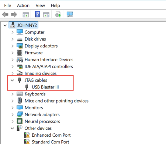
- If USB Blaster III isn’t showed, please check whether the Other devices has Unknown device.
If yes, please refer to the steps described in this link:Altera USB Blaster II Driver Installation Instructions to install the USB blaster III driver. The installation steps are generic, you just need to select the USB Blaster III driver located in the Quartus installation directory.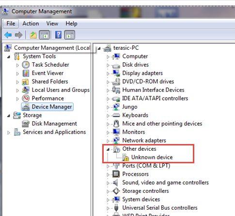 .
.
- If no Unknown device:


- i.Make sure the board power is on and the port on board which connected to PC is USB blaster III port.
- ii.If step i is OK:
- a.Test with another PC to see if the OS can detect unknown device.
- b.Test with another USB blaster III cable.
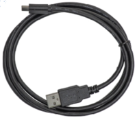
- c.If still with the same problem, please contact our technical support team via support@terasic.com and provide below information:
- PC OS version: Win10-64bit, Win11-64bit or Linux-64bit.
- Whether you tested follow the above processes.
- The Quartus version you installed: Quartus Prime 25.1 or others.

FAQ
1. Q: What is the operating temperature specification of the UBT3?
A:The UBT3 is designed to operate in the industrial temperature range (-40°C to +85°C).
