DE10 Advance revC demo: Factory Default Code
From Terasic Wiki
(Difference between revisions)
(Created page with "The DE10-Advanced board has a default configuration bit-stream pre-programmed, which demonstrates some of the basic features on board. This demo used LED ,7-Segments, Switch , HD...") |
|||
| Line 1: | Line 1: | ||
The DE10-Advanced board has a default configuration bit-stream pre-programmed, which demonstrates some of the basic features on board. This demo used LED ,7-Segments, Switch , | The DE10-Advanced board has a default configuration bit-stream pre-programmed, which demonstrates some of the basic features on board. This demo used LED ,7-Segments, Switch , | ||
HDMI transmitter display and fan control. | HDMI transmitter display and fan control. | ||
| + | |||
| + | =Function Block Diagram= | ||
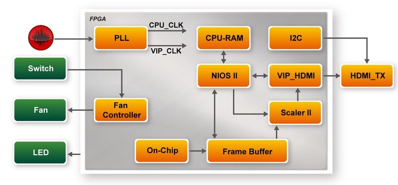
| + | Figure 2-1 shows the function block diagram of this demonstration..This demo used fan controller to control fan and used frame buffer read board picture from ON-CHIP-MEMORY,and used scaler scale the picture to 1920x1080 size,display the picture by HDMI TX. | ||
| + | |||
| + | |||
| + | [[File:De10 advanced revc demo default code.jpg|800px]] | ||
| + | |||
| + | ::::::'''Figure 6-2 Block diagram of Default demonstration''' | ||
| + | =Design Tools= | ||
| + | |||
| + | *Quartus Prime 18.0.0 Standard Edition | ||
| + | *Demonstration Source Code: | ||
| + | **Project Directory: Demonstration\default_code | ||
| + | **Bit Stream: default_code.sof or default_code.jic | ||
| + | **Demonstration Batch File: default_code\demo_batch or default_code\demo_run_batch | ||
| + | |||
| + | NOTE : because the demo include software , and run on on-chip-memory, so use mem_init can package elf to sof ,so user can only program sof or sof +elf to run demo | ||
| + | |||
| + | The demo batch file includes following files: | ||
| + | :*Batch File: test.bat | ||
| + | :*FPGA Configuration File: default_code.sof or default_code.jic | ||
| + | |||
| + | =Demonstration Setup= | ||
| + | |||
| + | #Make sure Quartus Prime is installed on the host PC. | ||
| + | #Connect DE10-Advanced board to the host PC via USB cable. Install the USB-Blaster II driver if necessary. | ||
| + | #Connect the HDMI TX to displayer via HDMI cable. | ||
| + | #Power on the DE10-Advanced. | ||
| + | #Execute the demo batch file “test.bat” under the batch file folder \ default_code\demo_batch. You will see the menu Figure 6-3 | ||
| + | #Select your choice,and program FPGA or program flash | ||
| + | #When the demo is running , you can see the led is blinking and flowing, and the displayer will display the board picture Figure 6-4 | ||
Revision as of 15:40, 23 August 2018
The DE10-Advanced board has a default configuration bit-stream pre-programmed, which demonstrates some of the basic features on board. This demo used LED ,7-Segments, Switch , HDMI transmitter display and fan control.
Function Block Diagram
Figure 2-1 shows the function block diagram of this demonstration..This demo used fan controller to control fan and used frame buffer read board picture from ON-CHIP-MEMORY,and used scaler scale the picture to 1920x1080 size,display the picture by HDMI TX.
- Figure 6-2 Block diagram of Default demonstration
Design Tools
- Quartus Prime 18.0.0 Standard Edition
- Demonstration Source Code:
- Project Directory: Demonstration\default_code
- Bit Stream: default_code.sof or default_code.jic
- Demonstration Batch File: default_code\demo_batch or default_code\demo_run_batch
NOTE : because the demo include software , and run on on-chip-memory, so use mem_init can package elf to sof ,so user can only program sof or sof +elf to run demo
The demo batch file includes following files:
- Batch File: test.bat
- FPGA Configuration File: default_code.sof or default_code.jic
Demonstration Setup
- Make sure Quartus Prime is installed on the host PC.
- Connect DE10-Advanced board to the host PC via USB cable. Install the USB-Blaster II driver if necessary.
- Connect the HDMI TX to displayer via HDMI cable.
- Power on the DE10-Advanced.
- Execute the demo batch file “test.bat” under the batch file folder \ default_code\demo_batch. You will see the menu Figure 6-3
- Select your choice,and program FPGA or program flash
- When the demo is running , you can see the led is blinking and flowing, and the displayer will display the board picture Figure 6-4
