Terasic's Developer Kit for Intel Pathfinder for RISC-V QSG
From Terasic Wiki
(→Chpater2 What's in the Box?) |
(→Chpater3 Software Installation) |
||
| (43 intermediate revisions not shown) | |||
| Line 2: | Line 2: | ||
'''Terasic's Developer Kit for Intel Pathfinder for RISC-V''' uses Terasic's most classic '''DE2-115''' FPGA development board as a carrier to implement various RISC-V designs of Intel Pathfinder for RISC-V project. When used for Intel Pathfinder for RISC-V project, we will take another name of DE2-115 as '''PR-115'''. In the following contents, we will call Terasic's Developer Kit for Intel Pathfinder for RISC-V to '''PR-115''' board. | '''Terasic's Developer Kit for Intel Pathfinder for RISC-V''' uses Terasic's most classic '''DE2-115''' FPGA development board as a carrier to implement various RISC-V designs of Intel Pathfinder for RISC-V project. When used for Intel Pathfinder for RISC-V project, we will take another name of DE2-115 as '''PR-115'''. In the following contents, we will call Terasic's Developer Kit for Intel Pathfinder for RISC-V to '''PR-115''' board. | ||
| - | In this document, we will introduce many basic instructions of PR-115 board for users, such as installing | + | In this document, we will introduce many basic instructions of PR-115 board for users, such as installing the USB Blaster driver, performing power on test, etc., so that users can quickly get started on the development board. |
= <span style="color:#000080;">Chpater2 What's in the Box?</span> = | = <span style="color:#000080;">Chpater2 What's in the Box?</span> = | ||
| - | [[File:PR-115 kit content.jpg| | + | [[File:PR-115 kit content.jpg|400px]] |
#Terasic's Developer Kit for Intel® Pathfinder for RISC-V | #Terasic's Developer Kit for Intel® Pathfinder for RISC-V | ||
| Line 16: | Line 16: | ||
= <span style="color:#000080;">Chpater3 Software Installation</span> = | = <span style="color:#000080;">Chpater3 Software Installation</span> = | ||
| - | + | *<span style="color:#000080;">'''Resources of the Intel® Pathfinder for RISC-V'''</span> | |
| + | *:Please go to the official website of the Intel® Pathfinder for RISC-V* to register account to get the resources of the Intel® Pathfinder. | ||
| + | *:Website:[https://pathfinder.intel.com/ pathfinder.intel.com] | ||
| - | Please refer to the follwing link to download the '''Intel Quartus Prime''' software and install to your Host PC : [https://www.intel.com/content/www/us/en/products/details/fpga/development-tools/quartus-prime/resource.html Download Intel® Quartus® Prime Software] | + | *<span style="color:#000080;">'''Intel Quartus Prime'''</span> |
| + | *:Before using Intel FPGA to develop a user's project, the user first needs to install the '''Intel Quartus Prime''' software on your Host PC.The '''Intel Quartus Prime''' software is available in three editions based on design requirements: '''Pro''', '''Standard''', and '''Lite''' Edition. The Pro and Standard edition will need users to purchase license file. The lite edition provides an ideal entry point to high-volume device families and is available as a free download with no license file required. The following link shows the compare contents of these three edition: [https://www.intel.com/content/dam/www/central-libraries/us/en/documents/quartus-prime-compare-editions-guide.pdf Compare Editions]. The FPGA device on the PR-115 board is Intel Cyclone IV device family and it can be supported by the Quartus Prime Lite edition. | ||
| + | *:Please refer to the follwing link to download the '''Intel Quartus Prime''' software and install to your Host PC : [https://www.intel.com/content/www/us/en/products/details/fpga/development-tools/quartus-prime/resource.html Download Intel® Quartus® Prime Software] | ||
= <span style="color:#000080;">Chpater4 Perform Power-on Test </span> = | = <span style="color:#000080;">Chpater4 Perform Power-on Test </span> = | ||
| + | This chapter can lead the user to quickly power on the board and observe some basic status of the board. | ||
| + | #Plug the supplied 12V DC power supply into an AC power outlet(100V~240V), and then connect this power supply to the power connector (J8) of the development board. | ||
| + | #: | ||
| + | #:[[File:PR 115 QSG PWR Adapter.jpg|500px]] | ||
| + | #: | ||
| + | #: | ||
| + | #Power up the development board by pressing the red power switch button(SW18). | ||
| + | #There is factory FPGA code inside the board, so Power-on test is successful if you observe the following: | ||
| + | #*Eight 7-SEGs count up repeatedly | ||
| + | #*Flashing red and green LEDs | ||
| + | #*LCD displays default characters | ||
| + | #*If you connect the '''VGA''' output (J13) to a standard VGA display, a 256-colored image will be seen. | ||
| + | #:[[File:PR-115 VGA Cable.jpg|350px]] | ||
| + | |||
| + | = <span style="color:#000080;">Chpater5 Install USB Blaster Driver </span> = | ||
| + | The development board equipped with an USB-Blaster circuit, it interfaces a USB port on a host computer to the FPGA device on the board. The USB-Blaster circuit sends configuration data from the PC via the JTAG interface to the FPGA. To use USB-Blaster circuit, user need to install the driver on your operation system. | ||
| + | |||
| + | To install the USB Blaster driver to your host PC, please refer to the following instruction to setup the driver installation. | ||
| + | |||
| + | #Plug the supplied 12V DC power supply into an AC power outlet (100V-240V), and then connect this power supply to the development board (J8) | ||
| + | #Connect the development board to the Host PC using the supplied USB cable from the USB Blaster Port(J9). | ||
| + | #:[[File:PR-115 USB TypeB Cable.jpg|350px]] | ||
| + | #Power up the board by pressing the red power switch button (SW18). | ||
| + | #For '''Windows 10''' system users, please refer to the following link to install the driver on your windows system :[[Intel USB Blaster Driver Installation Instructions]]. | ||
| + | #For '''Linux''' system users, please refer to the following link to install the driver on your windows system :[https://www.rocketboards.org/foswiki/Documentation/UsingUSBBlasterUnderLinux Using USB Blaster / USB Blaster II under Linux]. | ||
| + | |||
| + | = <span style="color:#000080;">Chpater6 Contents of the FPGA Design Package for Development Board </span> = | ||
| + | Terasic's Developer Kit for Intel Pathfinder for RISC-V uses Terasic's most classic DE2-115 FPGA development board as a carrier to implement various RISC-V designs of Intel Pathfinder for RISC-V project. Therefore, the content of The FPGA Design Package for Development Board is the DE2-115 System CD. If the user needs the hardware information or more FPGA demonstrations of this development board, please refer to this DE2-115 System CD to get more information about this board. Users can go the [https://www.terasic.com.tw/cgi-bin/page/archive.pl?Language=English&CategoryNo=139&No=1301&PartNo=4#contents "Resource"] tab of the PR-115 website to download the FPGA Design Package for Development Board. | ||
| + | The following information is the content of the DE2-115 System CD. | ||
| + | |||
| + | <div style="text-align:left;"> '''DE2-115 System CD Contents'''</div> | ||
| + | |||
| + | {| align="left" style="border-spacing:0;width:14.651cm;" | ||
| + | |- | ||
| + | | style="background-color:#bfbfbf;border-top:0.5pt solid #000000;border-bottom:0.5pt solid #000000;border-left:0.5pt solid #000000;border-right:none;padding-top:0cm;padding-bottom:0cm;padding-left:0.191cm;padding-right:0.191cm;color:#000000;" | '''Directory Name''' | ||
| + | | style="background-color:#bfbfbf;border:0.5pt solid #000000;padding-top:0cm;padding-bottom:0cm;padding-left:0.191cm;padding-right:0.191cm;color:#000000;" | '''Contents''' | ||
| + | |- | ||
| + | | style="border-top:0.5pt solid #000000;border-bottom:0.5pt solid #000000;border-left:0.5pt solid #000000;border-right:none;padding-top:0cm;padding-bottom:0cm;padding-left:0.191cm;padding-right:0.191cm;color:#000000;" | DE2-115_tools | ||
| + | | style="border:0.5pt solid #000000;padding-top:0cm;padding-bottom:0cm;padding-left:0.191cm;padding-right:0.191cm;color:#000000;" | DE2-115 System Builder and Control Panel utility | ||
| + | |- | ||
| + | | style="border-top:0.5pt solid #000000;border-bottom:0.5pt solid #000000;border-left:0.5pt solid #000000;border-right:none;padding-top:0cm;padding-bottom:0cm;padding-left:0.191cm;padding-right:0.191cm;color:#000000;" | DE2_115_datasheets | ||
| + | | style="border:0.5pt solid #000000;padding-top:0cm;padding-bottom:0cm;padding-left:0.191cm;padding-right:0.191cm;color:#000000;" | Datasheets of the components on the DE2-115 | ||
| + | |- | ||
| + | | style="border-top:0.5pt solid #000000;border-bottom:0.5pt solid #000000;border-left:0.5pt solid #000000;border-right:none;padding-top:0cm;padding-bottom:0cm;padding-left:0.191cm;padding-right:0.191cm;color:#000000;" | DE2_115_demonstrations | ||
| + | | style="border:0.5pt solid #000000;padding-top:0cm;padding-bottom:0cm;padding-left:0.191cm;padding-right:0.191cm;color:#000000;" | Versatile projects illustrating the capabilities of the DE2-115 | ||
| + | |- | ||
| + | | style="border-top:0.5pt solid #000000;border-bottom:0.5pt solid #000000;border-left:0.5pt solid #000000;border-right:none;padding-top:0cm;padding-bottom:0cm;padding-left:0.191cm;padding-right:0.191cm;color:#000000;" | DE2_115_lab_exercises | ||
| + | | style="border:0.5pt solid #000000;padding-top:0cm;padding-bottom:0cm;padding-left:0.191cm;padding-right:0.191cm;color:#000000;" |Drills from simple digital logic circuits to complicated MCU projects | ||
| + | |- | ||
| + | | style="border-top:0.5pt solid #000000;border-bottom:0.5pt solid #000000;border-left:0.5pt solid #000000;border-right:none;padding-top:0cm;padding-bottom:0cm;padding-left:0.191cm;padding-right:0.191cm;color:#000000;" | DE2_115_schematic | ||
| + | | style="border:0.5pt solid #000000;padding-top:0cm;padding-bottom:0cm;padding-left:0.191cm;padding-right:0.191cm;color:#000000;" |Schematic of the DE2-115 | ||
| + | |- | ||
| + | | style="border-top:0.5pt solid #000000;border-bottom:0.5pt solid #000000;border-left:0.5pt solid #000000;border-right:none;padding-top:0cm;padding-bottom:0cm;padding-left:0.191cm;padding-right:0.191cm;color:#000000;" | DE2_115_tutorials | ||
| + | | style="border:0.5pt solid #000000;padding-top:0cm;padding-bottom:0cm;padding-left:0.191cm;padding-right:0.191cm;color:#000000;" |Fundamental knowledge of developing FPGA based systems | ||
| + | |- | ||
| + | | style="border-top:0.5pt solid #000000;border-bottom:0.5pt solid #000000;border-left:0.5pt solid #000000;border-right:none;padding-top:0cm;padding-bottom:0cm;padding-left:0.191cm;padding-right:0.191cm;color:#000000;" | DE2_115_user_manual | ||
| + | | style="border:0.5pt solid #000000;padding-top:0cm;padding-bottom:0cm;padding-left:0.191cm;padding-right:0.191cm;color:#000000;" |Reference information for using the DE2-115 | ||
| + | |- | ||
| + | |} | ||
Latest revision as of 17:55, 19 August 2022
Contents |
Chpater1 Introduction
Terasic's Developer Kit for Intel Pathfinder for RISC-V uses Terasic's most classic DE2-115 FPGA development board as a carrier to implement various RISC-V designs of Intel Pathfinder for RISC-V project. When used for Intel Pathfinder for RISC-V project, we will take another name of DE2-115 as PR-115. In the following contents, we will call Terasic's Developer Kit for Intel Pathfinder for RISC-V to PR-115 board.
In this document, we will introduce many basic instructions of PR-115 board for users, such as installing the USB Blaster driver, performing power on test, etc., so that users can quickly get started on the development board.
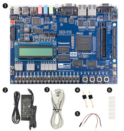
Chpater2 What's in the Box?
- Terasic's Developer Kit for Intel® Pathfinder for RISC-V
- Power DC Adaptor 12V/2A
- USB Programing Cable
- Two 1-pin Headers
- Two Wire Strips (black & red)
- Six Silicon Footstands
Chpater3 Software Installation
- Resources of the Intel® Pathfinder for RISC-V
- Please go to the official website of the Intel® Pathfinder for RISC-V* to register account to get the resources of the Intel® Pathfinder.
- Website:pathfinder.intel.com
- Intel Quartus Prime
- Before using Intel FPGA to develop a user's project, the user first needs to install the Intel Quartus Prime software on your Host PC.The Intel Quartus Prime software is available in three editions based on design requirements: Pro, Standard, and Lite Edition. The Pro and Standard edition will need users to purchase license file. The lite edition provides an ideal entry point to high-volume device families and is available as a free download with no license file required. The following link shows the compare contents of these three edition: Compare Editions. The FPGA device on the PR-115 board is Intel Cyclone IV device family and it can be supported by the Quartus Prime Lite edition.
- Please refer to the follwing link to download the Intel Quartus Prime software and install to your Host PC : Download Intel® Quartus® Prime Software
Chpater4 Perform Power-on Test
This chapter can lead the user to quickly power on the board and observe some basic status of the board.
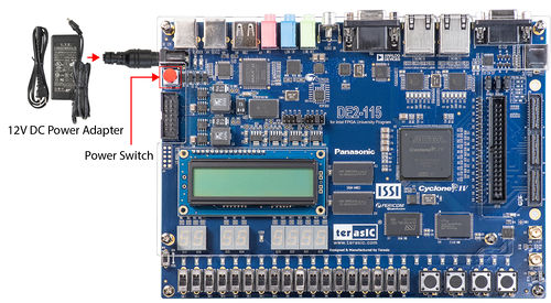
- Plug the supplied 12V DC power supply into an AC power outlet(100V~240V), and then connect this power supply to the power connector (J8) of the development board.
- Power up the development board by pressing the red power switch button(SW18).
- There is factory FPGA code inside the board, so Power-on test is successful if you observe the following:
- Eight 7-SEGs count up repeatedly
- Flashing red and green LEDs
- LCD displays default characters
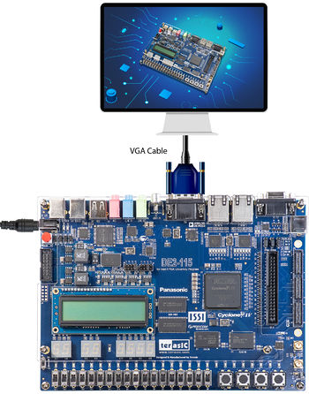
- If you connect the VGA output (J13) to a standard VGA display, a 256-colored image will be seen.
Chpater5 Install USB Blaster Driver
The development board equipped with an USB-Blaster circuit, it interfaces a USB port on a host computer to the FPGA device on the board. The USB-Blaster circuit sends configuration data from the PC via the JTAG interface to the FPGA. To use USB-Blaster circuit, user need to install the driver on your operation system.
To install the USB Blaster driver to your host PC, please refer to the following instruction to setup the driver installation.
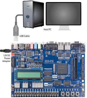
- Plug the supplied 12V DC power supply into an AC power outlet (100V-240V), and then connect this power supply to the development board (J8)
- Connect the development board to the Host PC using the supplied USB cable from the USB Blaster Port(J9).
- Power up the board by pressing the red power switch button (SW18).
- For Windows 10 system users, please refer to the following link to install the driver on your windows system :Intel USB Blaster Driver Installation Instructions.
- For Linux system users, please refer to the following link to install the driver on your windows system :Using USB Blaster / USB Blaster II under Linux.
Chpater6 Contents of the FPGA Design Package for Development Board
Terasic's Developer Kit for Intel Pathfinder for RISC-V uses Terasic's most classic DE2-115 FPGA development board as a carrier to implement various RISC-V designs of Intel Pathfinder for RISC-V project. Therefore, the content of The FPGA Design Package for Development Board is the DE2-115 System CD. If the user needs the hardware information or more FPGA demonstrations of this development board, please refer to this DE2-115 System CD to get more information about this board. Users can go the "Resource" tab of the PR-115 website to download the FPGA Design Package for Development Board. The following information is the content of the DE2-115 System CD.
| Directory Name | Contents |
| DE2-115_tools | DE2-115 System Builder and Control Panel utility |
| DE2_115_datasheets | Datasheets of the components on the DE2-115 |
| DE2_115_demonstrations | Versatile projects illustrating the capabilities of the DE2-115 |
| DE2_115_lab_exercises | Drills from simple digital logic circuits to complicated MCU projects |
| DE2_115_schematic | Schematic of the DE2-115 |
| DE2_115_tutorials | Fundamental knowledge of developing FPGA based systems |
| DE2_115_user_manual | Reference information for using the DE2-115 |


