Word2wiki bal user gide src
From Terasic Wiki
(→a) |
(→1-7 Using the IR Controller) |
||
| (26 intermediate revisions not shown) | |||
| Line 616: | Line 616: | ||
<div style="color:#000080;"></div> | <div style="color:#000080;"></div> | ||
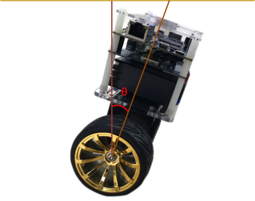
| - | The idealized state of the balance car is to maintain a vertical 90-degree angle to the ground. However, there are only two wheels support the body, which is more likely to lean forward or backward. It actually exists an angle of θ showing as Figure 1- . Our aim is to read out this angle and feed it back to the balance system for controlling the motor rotating in the opposite direction. In this way, it will make the tilt of the Angle to become the ideal 0 degree as a correction. | + | The idealized state of the balance car is to maintain a vertical 90-degree angle to the ground. However, there are only two wheels support the body, which is more likely to lean forward or backward. It actually exists an angle of θ showing as Figure 1-10 . Our aim is to read out this angle and feed it back to the balance system for controlling the motor rotating in the opposite direction. In this way, it will make the tilt of the Angle to become the ideal 0 degree as a correction. |
<div style="text-align:center;">[[Image: BAL_04_User_Guide_pic_10.png|500px]]</div> | <div style="text-align:center;">[[Image: BAL_04_User_Guide_pic_10.png|500px]]</div> | ||
| - | <div style="text-align:center;"> '''Figure 1- The tilted angle of the balance car'''</div> | + | <div style="text-align:center;"> '''Figure 1-10 The tilted angle of the balance car'''</div> |
| Line 627: | Line 627: | ||
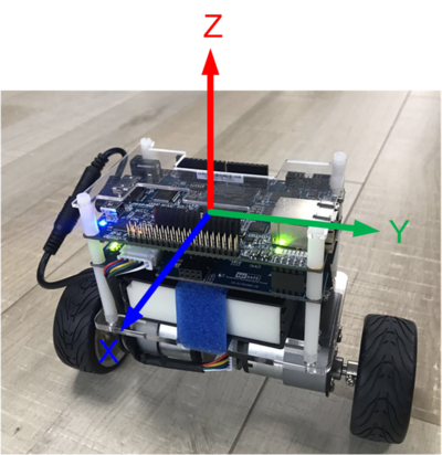
| - | First of all, we need to obtain the status of the XYZ coordinates of the MPU-6500 in the robot. From Figure 1- , It can be seen if the balance of the car is tilted forward or backward, corresponding changes resulting the acceleration of the X-axis and Y-axis. Meanwhile, the angular velocity of the Y-axis will also change. | + | First of all, we need to obtain the status of the XYZ coordinates of the MPU-6500 in the robot. From Figure 1-11 , It can be seen if the balance of the car is tilted forward or backward, corresponding changes resulting the acceleration of the X-axis and Y-axis. Meanwhile, the angular velocity of the Y-axis will also change. |
| - | <div style="text-align:center;">[[Image: BAL_04_User_Guide_pic_11.png| | + | <div style="text-align:center;">[[Image: BAL_04_User_Guide_pic_11.png|400px]]</div> |
| - | <div style="text-align:center;"> '''Figure 1- Status of the XYZ coordinates on the mpu-6500'''</div> | + | <div style="text-align:center;"> '''Figure 1-11 Status of the XYZ coordinates on the mpu-6500'''</div> |
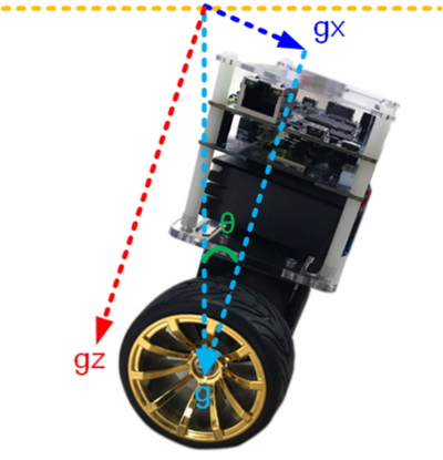
| - | Continue to introduce how to calculate the tilt angle of the balance car from the accelerometer. Figure 1- , ignore the horizontal acceleration of the car, there is a vertical angle θ when body tilts forward or backward. G is for the acceleration of gravity. Resolve g vector into X and Z directions, gx and gz are coordinate components for X-axis and Z-axis respectively, θ is the tangent angle of gx or gz. Read out the values of gx & gz from the accelerometer in the MPU-6500. Get the degree of angle θ by using the function θ = arctan(gx/gz). | + | Continue to introduce how to calculate the tilt angle of the balance car from the accelerometer. Figure 1-2 , ignore the horizontal acceleration of the car, there is a vertical angle θ when body tilts forward or backward. G is for the acceleration of gravity. Resolve g vector into X and Z directions, gx and gz are coordinate components for X-axis and Z-axis respectively, θ is the tangent angle of gx or gz. Read out the values of gx & gz from the accelerometer in the MPU-6500. Get the degree of angle θ by using the function θ = arctan(gx/gz). |
| - | <div style="text-align:center;">[[Image: BAL_04_User_Guide_pic_12.png| | + | <div style="text-align:center;">[[Image: BAL_04_User_Guide_pic_12.png|400px]]</div> |
| - | <div style="text-align:center;"> '''Figure 1- The tilted angle of the self-balance Robot'''</div> | + | <div style="text-align:center;"> '''Figure 1-2 The tilted angle of the self-balance Robot'''</div> |
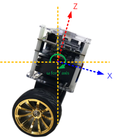
| - | Besides, it can also get the body tilted angle from Y-axis angular rate by using the gyroscope in the MPU-6500. See below Figure 1- , when the body tilts, the angular rate changes as well. Obtain the angle in Y-axis via doing the integral calculation on the angular rate. | + | Besides, it can also get the body tilted angle from Y-axis angular rate by using the gyroscope in the MPU-6500. See below Figure 1-13 , when the body tilts, the angular rate changes as well. Obtain the angle in Y-axis via doing the integral calculation on the angular rate. |
| - | <div style="text-align:center;">[[Image: BAL_04_User_Guide_pic_13.png| | + | <div style="text-align:center;">[[Image: BAL_04_User_Guide_pic_13.png|400px]]</div> |
| - | <div style="text-align:center;"> '''Figure 1- The tilted angle of the self-balance Robot'''</div> | + | <div style="text-align:center;"> '''Figure 1-13 The tilted angle of the self-balance Robot'''</div> |
| Line 654: | Line 654: | ||
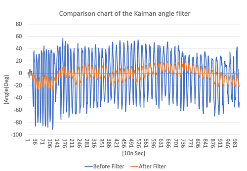
| - | Figure 1- shows the comparison of the original tilt Angle (blue) and the Angle (orange) by Kalman Filter. From the figure, you can see that the change in angle is large different for unfiltered angle (blue). By working with these data, the balance of the car body could not be stable. However, the varying amplitude for the orange Angle after filtering is significantly reduced. | + | Figure 1-14 shows the comparison of the original tilt Angle (blue) and the Angle (orange) by Kalman Filter. From the figure, you can see that the change in angle is large different for unfiltered angle (blue). By working with these data, the balance of the car body could not be stable. However, the varying amplitude for the orange Angle after filtering is significantly reduced. |
<div style="text-align:center;">[[Image: BAL_04_User_Guide_pic_14.png|500px]]</div> | <div style="text-align:center;">[[Image: BAL_04_User_Guide_pic_14.png|500px]]</div> | ||
| - | <div style="text-align:center;"> '''Figure 1- Comparison chart of the Kalman angle filter'''</div> | + | <div style="text-align:center;"> '''Figure 1-14 Comparison chart of the Kalman angle filter'''</div> |
| Line 741: | Line 741: | ||
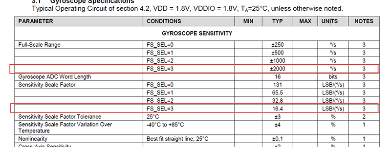
| - | <div style="text-align:center;">[[Image: BAL_04_User_Guide_pic_15.png| | + | <div style="text-align:center;">[[Image: BAL_04_User_Guide_pic_15.png|1000px]]</div> |
| - | <div style="text-align:center;">'''Figure 1- MPU-6500 datasheet-Gyroscope Specifications'''</div> | + | <div style="text-align:center;">'''Figure 1-15 MPU-6500 datasheet-Gyroscope Specifications'''</div> |
| Line 759: | Line 759: | ||
The parameters above will be provided to system for balance PID(Proportional–Integral–Derivative) controlling to feed back the actual condition of the body to achieve a balanced state. | The parameters above will be provided to system for balance PID(Proportional–Integral–Derivative) controlling to feed back the actual condition of the body to achieve a balanced state. | ||
| - | |||
| - | |||
== 1-4 Detect Obstacle Distance == | == 1-4 Detect Obstacle Distance == | ||
| Line 769: | Line 767: | ||
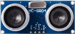
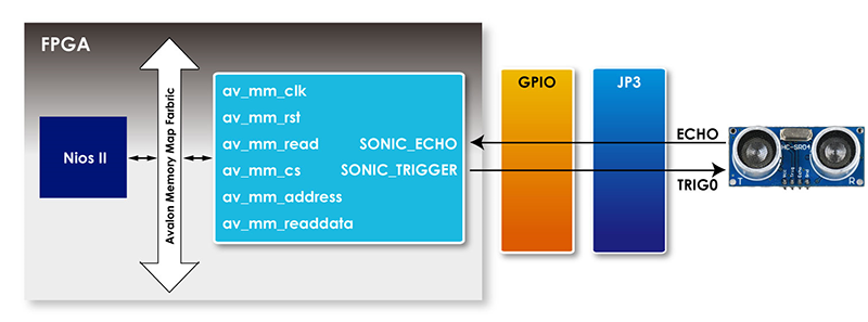
| - | As shown in Figure 1- , the robot assembled HC-SR04 Ultrasonic module. Besides VCC and GND pin, the module is controlled mainly by TRIG and ECHO signal. | + | As shown in Figure 1-16 , the robot assembled HC-SR04 Ultrasonic module. Besides VCC and GND pin, the module is controlled mainly by TRIG and ECHO signal. |
| Line 779: | Line 777: | ||
| + | <div style="text-align:center;"> [[Image: BAL_04_User_Guide_pic_16.png|300px]]</div> | ||
| - | <div style="text-align:center;"> | + | <div style="text-align:center;"> '''Figure 1-16 Ultrasonic module working diagram'''</div> |
| - | |||
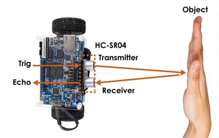
| + | <div style="text-align:center;">[[Image: BAL_04_User_Guide_pic_17.png|700px]]</div> | ||
| - | + | <div style="text-align:center;">'''Figure 1-17 Ultrasonic module working diagram'''</div> | |
| - | + | ||
| - | <div style="text-align:center;">'''Figure 1- Ultrasonic module working diagram'''</div> | + | |
| Line 800: | Line 797: | ||
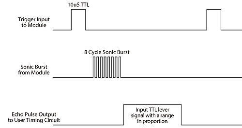
| - | <div style="text-align:center;">[[Image: BAL_04_User_Guide_pic_18. | + | <div style="text-align:center;">[[Image: BAL_04_User_Guide_pic_18.jpg|500px]]</div> |
| - | <div style="text-align:center;">'''Figure 1- Ultrasonic Module Timing Diagram'''</div> | + | <div style="text-align:center;">'''Figure 1-18 Ultrasonic Module Timing Diagram'''</div> |
| Line 816: | Line 813: | ||
| - | As shown in Figure 1- , the IP controls the TRIG pin, drives the module to start to detect obstacle, monitors whether there is reflection signal on ECHO pin and calculate the duration of the high level logic signal, then CPU will can read the data. | + | As shown in Figure 1-19 , the IP controls the TRIG pin, drives the module to start to detect obstacle, monitors whether there is reflection signal on ECHO pin and calculate the duration of the high level logic signal, then CPU will can read the data. |
| - | [[Image: BAL_04_User_Guide_pic_19.png| | + | <div style="text-align:center;">[[Image: BAL_04_User_Guide_pic_19.png|800px]] </div> |
| - | <div style="text-align:center;"> '''Figure 1- The IP symbol and block diagram'''</div> | + | <div style="text-align:center;"> '''Figure 1-19 The IP symbol and block diagram'''</div> |
| Line 830: | Line 827: | ||
<div style="color:#000080;"></div> | <div style="color:#000080;"></div> | ||
| - | Table 1- shows the register table of the IP. measure_value register stores the ultrasonic transmission time that the module detects the obstacle distance each time. | + | Table 1-4 shows the register table of the IP. measure_value register stores the ultrasonic transmission time that the module detects the obstacle distance each time. |
| - | <div style="text-align:center;">''' Table 1- <span style="color:#000000;">R</span><span style="color:#000000;">egister table of the IP'''</span></div> | + | <div style="text-align:center;">''' Table 1-4 <span style="color:#000000;">R</span><span style="color:#000000;">egister table of the IP'''</span></div> |
| Line 844: | Line 841: | ||
| style="background-color:#979797;border:0.75pt solid #797979;padding:0.026cm;" | '''Description''' | | style="background-color:#979797;border:0.75pt solid #797979;padding:0.026cm;" | '''Description''' | ||
|- | |- | ||
| - | | style="border-top:0.75pt solid #cccccc;border-bottom:0.75pt solid #cccccc;border-left:0.75pt solid #cccccc;border-right:none;padding:0.212cm;" | Base Addr + 0 | + | |rowspan="2" style="border-top:0.75pt solid #cccccc;border-bottom:0.75pt solid #cccccc;border-left:0.75pt solid #cccccc;border-right:none;padding:0.212cm;" | Base Addr + 0 |
| style="border-top:0.75pt solid #cccccc;border-bottom:0.75pt solid #cccccc;border-left:0.75pt solid #cccccc;border-right:none;padding:0.026cm;" | 31:22 | | style="border-top:0.75pt solid #cccccc;border-bottom:0.75pt solid #cccccc;border-left:0.75pt solid #cccccc;border-right:none;padding:0.026cm;" | 31:22 | ||
| style="border-top:0.75pt solid #cccccc;border-bottom:0.75pt solid #cccccc;border-left:0.75pt solid #cccccc;border-right:none;padding:0.026cm;" | RO | | style="border-top:0.75pt solid #cccccc;border-bottom:0.75pt solid #cccccc;border-left:0.75pt solid #cccccc;border-right:none;padding:0.026cm;" | RO | ||
| Line 857: | Line 854: | ||
|} | |} | ||
* <div style="color:#000080;">'''IP Code Description'''</div> | * <div style="color:#000080;">'''IP Code Description'''</div> | ||
| - | |||
| Line 956: | Line 952: | ||
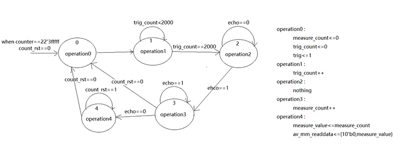
| - | Figure 1- is the state diagram of the State Machine in the IP. | + | Figure 1-20 is the state diagram of the State Machine in the IP. |
| - | [[Image: BAL_04_User_Guide_pic_20.png| | + | <div style="text-align:center;"> [[Image: BAL_04_User_Guide_pic_20.png|800px]] </div> |
<div style="text-align:center;"> '''Figure 1- State Diagram of the State Machine'''</div> | <div style="text-align:center;"> '''Figure 1- State Diagram of the State Machine'''</div> | ||
| Line 1,001: | Line 997: | ||
* <div style="color:#000080;">'''Software Code'''</div> | * <div style="color:#000080;">'''Software Code'''</div> | ||
| - | |||
| Line 1,017: | Line 1,012: | ||
<div style="margin-left:2.501cm;margin-right:0cm;"></div> | <div style="margin-left:2.501cm;margin-right:0cm;"></div> | ||
| + | |||
== 1-5 Balanced System == | == 1-5 Balanced System == | ||
| Line 1,026: | Line 1,022: | ||
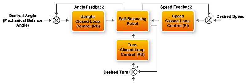
| - | The status control of the robot introduces the concept of PID (Proportional–Integral–Derivative) controller, the robot uses PD ( Proportional Derivative) or PI ( Proportional Integral) to control the balancing status, which are used for vertical angle control, rotation angle control and velocity control, respectively. As these three controls are closed loop controls, they are also called as '''balance loop''', '''turn loop''' and ''' | + | The status control of the robot introduces the concept of PID (Proportional–Integral–Derivative) controller, the robot uses PD ( Proportional Derivative) or PI ( Proportional Integral) to control the balancing status, which are used for vertical angle control, rotation angle control and velocity control, respectively. As these three controls are closed loop controls, they are also called as '''balance loop''', '''turn loop''' and '''speed loop''', respectively. The balance loop is controlled by PD controller, the velocity loop is controlled by PI controller, and the turn loop is controlled by PD controller. |
| Line 1,032: | Line 1,028: | ||
| - | The ''' | + | The '''speed loop''' is controlled by PI controller, which is the most commonly used control method for velocity control. PI controller is a linear control method. The deviation is formed according to the given value and the actual output value, then the Proportional (P) and Integral (I) of the deviation are composed of the control value by the linear combination, then the velocity can be controlled. The control value of P is velocity deviation, the control value of I is displacement. This loop corresponds to the'' int velocity (void)'' function in the software of our demo. |
| - | The turn | + | The '''turn loop''' is a simple control. In our demo, the turn value is measured by MPU-6500 Z-axis gyroscope and the difference of two speed encoders, which is used for D and P control value, respectively, so the rotation angle can be controlled by PD controller to ensure the angle keep the set value, and the response velocity of the robot can be improved by z-axis gyroscope control. This loop corresponds to the ''int turn(float Gyro)'' function in the software of our demo. |
| - | The block diagram of the three loops integrated function is shown in Figure 1- . | + | The block diagram of the three loops integrated function is shown in Figure 1-21 . |
| - | <div style="text-align:center;">[[Image: BAL_04_User_Guide_pic_21. | + | <div style="text-align:center;">[[Image: BAL_04_User_Guide_pic_21.jpg|800px]]</div> |
| - | <div style="text-align:center;"> '''Figure 1- PID closed-loop Control with Angle, Speed and Turn of the Robot'''</div> | + | <div style="text-align:center;"> '''Figure 1-21 PID closed-loop Control with Angle, Speed and Turn of the Robot'''</div> |
| Line 1,054: | Line 1,050: | ||
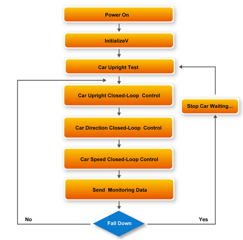
The status of the robot needs to be sampling controlled at regular intervals. In our demo, the interval time is 10ms. The sampling control of the angle, velocity and rotation angle can be implemented by executing the interrupt function void ''MPU_INT_ISR(void * contex, alt_u32 id)''. Meanwhile, the while function in the main code is used for polling the Bluetooth/IR control signal, ultrasonic detection obstacle distance (for obstacle avoidance) signal and power monitoring signal. | The status of the robot needs to be sampling controlled at regular intervals. In our demo, the interval time is 10ms. The sampling control of the angle, velocity and rotation angle can be implemented by executing the interrupt function void ''MPU_INT_ISR(void * contex, alt_u32 id)''. Meanwhile, the while function in the main code is used for polling the Bluetooth/IR control signal, ultrasonic detection obstacle distance (for obstacle avoidance) signal and power monitoring signal. | ||
| - | The main routine flow chart is shown in Figure 1- . | + | The main routine flow chart is shown in Figure 1-22 . |
<div style="text-align:center;">[[Image: BAL_04_User_Guide_pic_22.png|500px]]</div> | <div style="text-align:center;">[[Image: BAL_04_User_Guide_pic_22.png|500px]]</div> | ||
| - | <div style="text-align:center;"> '''Figure 1- Main Routine FLOW Chart'''</div> | + | <div style="text-align:center;"> '''Figure 1-22 Main Routine FLOW Chart'''</div> |
| - | + | ||
| - | + | ||
== 1-6 Use the Bluetooth == | == 1-6 Use the Bluetooth == | ||
| Line 1,068: | Line 1,062: | ||
| - | ESP32 is a powerful Bluetooth+WiFi module. It is easily developed. The Factory code in the ESP32 module has been written with ID Number of the Self-balancing robot, so it is able to accept the control command from mobile phone APP via Bluetooth connection. Besides it, there are also many other expandable functions such as I2C, WiFi and SPI data transmission, etc. However, in the robot, only the Bluetooth part is currently used, so only Bluetooth part is introduced. | + | ESP32 is a powerful Bluetooth+WiFi module. It is easily developed. The Factory code in the ESP32 module has been written with ID Number of the Self-balancing robot, so it is able to accept the control command from mobile phone APP via Bluetooth connection. Besides it, there are also many other expandable functions such as I2C, WiFi and SPI data transmission, etc. However, in the robot, only the Bluetooth part is currently used, so only Bluetooth part is introduced. |
| + | * <div style="color:#000080;">'''Example Descriptions'''</div> | ||
| - | + | ||
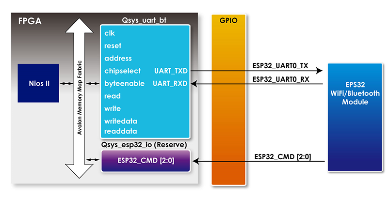
| + | Figure 1-23 is for the system architecture of Self-balancing robot using the ESP32. When the ESP32 receives the string command from the app via the Bluetooth protocol, it will be transferred to the UART interface and pass to the UART IP of the QSYS within the FPGA. In this way, the NIOS CPU can easily read the value of the data register in the IP, and then compare it with the defined instruction to get an effective instruction and control the movement of the robot. | ||
| Line 1,078: | Line 1,074: | ||
| - | <div style="text-align:center;">[[Image: BAL_04_User_Guide_pic_23.png| | + | <div style="text-align:center;">[[Image: BAL_04_User_Guide_pic_23.png|800px]]</div> |
| - | <div style="text-align:center;"> '''Figure 1- The Block Diagram of the communication between EPS32 and FPGA'''</div> | + | <div style="text-align:center;"> '''Figure 1-23 The Block Diagram of the communication between EPS32 and FPGA'''</div> |
| Line 1,088: | Line 1,084: | ||
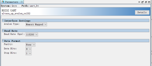
| - | The settings for the UART IP is as Figure 1- , Baud Rate set as115200. | + | The settings for the UART IP is as Figure 1-24 , Baud Rate set as115200. |
<div style="text-align:center;">[[Image: BAL_04_User_Guide_pic_24.png|500px]]</div> | <div style="text-align:center;">[[Image: BAL_04_User_Guide_pic_24.png|500px]]</div> | ||
| - | <div style="text-align:center;"> '''Figure 1- Qsys uart IP Settings'''</div> | + | <div style="text-align:center;"> '''Figure 1-24 Qsys uart IP Settings'''</div> |
| - | As shown in Table 1- , the UART IP contains two registers: Data Register & Control Register. The read and write FIFOs are accessed via the data register. The Data transmitted via bluetooth will be stored here. RS232 UART Core’s interrupt generation and read-status information are controlled by the Control register. | + | As shown in Table 1-5 , the UART IP contains two registers: Data Register & Control Register. The read and write FIFOs are accessed via the data register. The Data transmitted via bluetooth will be stored here. RS232 UART Core’s interrupt generation and read-status information are controlled by the Control register. |
| - | <div style="text-align:center;"> '''Table 1- RS232 UART Core register map'''</div> | + | <div style="text-align:center;"> '''Table 1-5 RS232 UART Core register map'''</div> |
| - | + | ||
{| align="center" style="border-spacing:0;width:16.159cm;" | {| align="center" style="border-spacing:0;width:16.159cm;" | ||
|- | |- | ||
| - | | align=center style="background-color:#979797;border-top:0.5pt solid #000000;border-bottom:0.5pt solid #000000;border-left:0.5pt solid #000000;border-right:none;padding:0.212cm;" | '''Offset in bytes''' | + | | rowspan="2" align=center style="background-color:#979797;border-top:0.5pt solid #000000;border-bottom:0.5pt solid #000000;border-left:0.5pt solid #000000;border-right:none;padding:0.212cm;" | '''Offset in bytes''' |
| - | | style="background-color:#979797;border-top:0.5pt solid #000000;border-bottom:0.5pt solid #000000;border-left:0.5pt solid #000000;border-right:none;padding:0.026cm;" | '''Register''' | + | | rowspan="2" style="background-color:#979797;border-top:0.5pt solid #000000;border-bottom:0.5pt solid #000000;border-left:0.5pt solid #000000;border-right:none;padding:0.026cm;" | '''Register''' |
'''Name''' | '''Name''' | ||
| - | | align=center style="background-color:#979797;border-top:0.5pt solid #000000;border-bottom:0.5pt solid #000000;border-left:0.5pt solid #000000;border-right:none;padding:0.026cm;" | '''R/W''' | + | | rowspan="2" align=center style="background-color:#979797;border-top:0.5pt solid #000000;border-bottom:0.5pt solid #000000;border-left:0.5pt solid #000000;border-right:none;padding:0.026cm;" | '''R/W''' |
| colspan="13" align=center style="background-color:#979797;border:0.5pt solid #000000;padding:0.212cm;" | <span style="background-color:#979797;">'''Bit description'''</span> | | colspan="13" align=center style="background-color:#979797;border:0.5pt solid #000000;padding:0.212cm;" | <span style="background-color:#979797;">'''Bit description'''</span> | ||
|- | |- | ||
| Line 1,158: | Line 1,153: | ||
| - | Table 1- shows the Data Register format, the bit 8~0 are for the data transferring, bit 23~16 are for indicating the number of characters remaining in the read FIFO. We can know the data transmission completed or not via bit 23~16. | + | Table 1-6 shows the Data Register format, the bit 8~0 are for the data transferring, bit 23~16 are for indicating the number of characters remaining in the read FIFO. We can know the data transmission completed or not via bit 23~16. |
| - | + | ||
| - | + | ||
| + | <div style="text-align:center;"> '''Table 1-6 Data register bits'''</div> | ||
{| align="center" style="border-spacing:0;width:15.87cm;" | {| align="center" style="border-spacing:0;width:15.87cm;" | ||
| Line 1,198: | Line 1,192: | ||
|} | |} | ||
<div style="text-align:center;"></div> | <div style="text-align:center;"></div> | ||
| + | |||
The following will introduce how to use Nios to read the data transmitted by ESP32 and convert it to control commands. In the main.cpp (path:\BAL_CAR_Nios_Code\software\DE10_Nano_bal), the codes for Bluetooth controlling as below: | The following will introduce how to use Nios to read the data transmitted by ESP32 and convert it to control commands. In the main.cpp (path:\BAL_CAR_Nios_Code\software\DE10_Nano_bal), the codes for Bluetooth controlling as below: | ||
| Line 1,406: | Line 1,401: | ||
<span style="color:#7f0055;">'''char'''</span> Data[10]={0}; | <span style="color:#7f0055;">'''char'''</span> Data[10]={0}; | ||
| - | nNum | + | nNum |
| - | + | ||
| + | '''sizeof'''(gCommandList)/<span style= | ||
"color:#7f0055;">'''sizeof'''</span>(gCommandList[0]); | "color:#7f0055;">'''sizeof'''</span>(gCommandList[0]); | ||
| Line 1,474: | Line 1,470: | ||
| - | The infrared remote controller included with the kit package is an infrared remote controller that uses the NEC protocol. It uses 38K HZ frequency modulation to emit control signals to the infrared receiver on the robot. The FPGA decoder IP will decode the signal to control the robot motion. | + | The infrared remote controller included with the kit package is an infrared remote controller that uses the NEC protocol. It uses 38K HZ frequency modulation to emit control signals to the infrared receiver on the robot. The FPGA decoder IP will decode the signal to control the robot motion. |
| - | + | ||
| + | * <span style="color:#000080;">'''Infrared Remote Controller Protocols'''</span> | ||
The NEC format composes of a Leader Code, a 16-bit Custom Code, and a 8-bit Key Code. The Leader Code is transmitted first, which contains 9ms carrier frequency and 4.5ms zero signal, then followed by 16-bit Client Code, 8-bit Key Code and 8-bit Inversed Key Code, which is the reverse value of the Key Code, the robot IR receiver can use the Inversed Key Code to verify the Key Code. | The NEC format composes of a Leader Code, a 16-bit Custom Code, and a 8-bit Key Code. The Leader Code is transmitted first, which contains 9ms carrier frequency and 4.5ms zero signal, then followed by 16-bit Client Code, 8-bit Key Code and 8-bit Inversed Key Code, which is the reverse value of the Key Code, the robot IR receiver can use the Inversed Key Code to verify the Key Code. | ||
| Line 1,483: | Line 1,479: | ||
The logic is judged through different time lengths, 560us carrier frequency plus 1690us 0 signal represents the transmission of logic 1, 560us carrier frequency plus 560us 0 signal represents logic 0. | The logic is judged through different time lengths, 560us carrier frequency plus 1690us 0 signal represents the transmission of logic 1, 560us carrier frequency plus 560us 0 signal represents logic 0. | ||
| - | <div style="text-align:center;"><span style="color:#4a4a4a;">[[Image: BAL_04_User_Guide_pic_25.png| | + | <div style="text-align:center;"><span style="color:#4a4a4a;">[[Image: BAL_04_User_Guide_pic_25.png|900px]]</span></div> |
| - | <div style="text-align:center;">'''Figure 1- NEC protocol leader & length variable block'''</div> | + | <div style="text-align:center;">'''Figure 1-25 NEC protocol leader & length variable block'''</div> |
| - | The IR receiver on the balanced car can decode the carrier frequency of 38 kHz and reverse the received signal. Therefore, it should be noted that the signal processed in the FPGA will be opposite to that of the transmitter, as shown in Figure 1- . | + | The IR receiver on the balanced car can decode the carrier frequency of 38 kHz and reverse the received signal. Therefore, it should be noted that the signal processed in the FPGA will be opposite to that of the transmitter, as shown in Figure 1-25 . |
| - | <div style="text-align:center;">[[Image: BAL_04_User_Guide_pic_26.png| | + | <div style="text-align:center;">[[Image: BAL_04_User_Guide_pic_26.png|900px]]</div> |
| - | <div style="text-align:center;"> '''Figure 1- The signal received by IR receiver '''</div> | + | <div style="text-align:center;"> '''Figure 1-26 The signal received by IR receiver '''</div> |
| Line 1,505: | Line 1,501: | ||
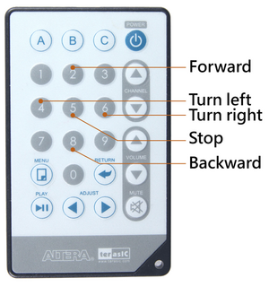
| - | <div style="text-align:center;">[[Image: BAL_04_User_Guide_pic_27.png| | + | <div style="text-align:center;">[[Image: BAL_04_User_Guide_pic_27.png|300px]]</div> |
| - | <div style="text-align:center;"> '''Figure 1- IR controller key function'''</div> | + | <div style="text-align:center;"> '''Figure 1-27 IR controller key function'''</div> |
<div style="color:#4a4a4a;"></div> | <div style="color:#4a4a4a;"></div> | ||
| - | <div style="text-align:center;">'''Table 1- Key code information for each Key on remote controller'''</div> | + | <div style="text-align:center;">'''Table 1-7 Key code information for each Key on remote controller'''</div> |
| - | + | ||
{| align="center" style="border-spacing:0;width:15.87cm;" | {| align="center" style="border-spacing:0;width:15.87cm;" | ||
|- | |- | ||
| - | | align=center style="background-color:#979797;border-top:0.5pt solid #000000;border-bottom:0.5pt solid #000000;border-left:0.5pt solid #000000;border-right:none;padding:0.212cm;" | '''IR Controller key''' | + | | rowspan="2" align=center style="background-color:#979797;border-top:0.5pt solid #000000;border-bottom:0.5pt solid #000000;border-left:0.5pt solid #000000;border-right:none;padding:0.212cm;width: 100px;" | '''IR Controller key''' |
| - | | colspan="2" align=center style="background-color:#979797;border-top:0.5pt solid #000000;border-bottom:0.5pt solid #000000;border-left:0.5pt solid #000000;border-right:none;padding:0.026cm;" | '''Custom Code''' | + | | colspan="2" align=center style="background-color:#979797;border-top:0.5pt solid #000000;border-bottom:0.5pt solid #000000;border-left:0.5pt solid #000000;border-right:none;padding:0.026cm;" | '''Custom Code''' |
| align=center style="background-color:#979797;border-top:0.5pt solid #000000;border-bottom:0.5pt solid #000000;border-left:0.5pt solid #000000;border-right:none;padding:0.026cm;" | '''Key code''' | | align=center style="background-color:#979797;border-top:0.5pt solid #000000;border-bottom:0.5pt solid #000000;border-left:0.5pt solid #000000;border-right:none;padding:0.026cm;" | '''Key code''' | ||
| align=center style="background-color:#979797;border:0.5pt solid #000000;padding:0.026cm;" | '''Inversed Key Code''' | | align=center style="background-color:#979797;border:0.5pt solid #000000;padding:0.026cm;" | '''Inversed Key Code''' | ||
| Line 1,527: | Line 1,522: | ||
| align=center style="background-color:#979797;border:0.5pt solid #000000;padding:0.026cm;" | '''D[27:24] D[31:28]''' | | align=center style="background-color:#979797;border:0.5pt solid #000000;padding:0.026cm;" | '''D[27:24] D[31:28]''' | ||
|- | |- | ||
| - | | align=center style="border-top:0.5pt solid #000000;border-bottom:0.5pt solid #000000;border-left:0.5pt solid #000000;border-right:none;padding:0. | + | | align=center style="border-top:0.5pt solid #000000;border-bottom:0.5pt solid #000000;border-left:0.5pt solid #000000;border-right:none;padding:0.026cm;" | [[Image: BAL_04_User_Guide_pic_28.png|250px]] |
| style="border-top:0.5pt solid #000000;border-bottom:0.5pt solid #000000;border-left:0.5pt solid #000000;border-right:none;padding:0.026cm;" | <span style="color:#4a4a4a;">6</span><span style="color:#4a4a4a;">8</span> | | style="border-top:0.5pt solid #000000;border-bottom:0.5pt solid #000000;border-left:0.5pt solid #000000;border-right:none;padding:0.026cm;" | <span style="color:#4a4a4a;">6</span><span style="color:#4a4a4a;">8</span> | ||
| style="border-top:0.5pt solid #000000;border-bottom:0.5pt solid #000000;border-left:0.5pt solid #000000;border-right:none;padding:0.026cm;" | <span style="color:#4a4a4a;">B</span><span style="color:#4a4a4a;">6</span> | | style="border-top:0.5pt solid #000000;border-bottom:0.5pt solid #000000;border-left:0.5pt solid #000000;border-right:none;padding:0.026cm;" | <span style="color:#4a4a4a;">B</span><span style="color:#4a4a4a;">6</span> | ||
| Line 1,533: | Line 1,528: | ||
| style="border:0.5pt solid #000000;padding:0.026cm;color:#4a4a4a;" | 0F | | style="border:0.5pt solid #000000;padding:0.026cm;color:#4a4a4a;" | 0F | ||
|- | |- | ||
| - | | style="border-top:0.5pt solid #000000;border-bottom:0.5pt solid #000000;border-left:0.5pt solid #000000;border-right:none;padding:0.026cm;" | [[Image: BAL_04_User_Guide_pic_29.png| | + | | style="border-top:0.5pt solid #000000;border-bottom:0.5pt solid #000000;border-left:0.5pt solid #000000;border-right:none;padding:0.026cm;" | [[Image: BAL_04_User_Guide_pic_29.png|250px]] |
| style="border-top:0.5pt solid #000000;border-bottom:0.5pt solid #000000;border-left:0.5pt solid #000000;border-right:none;padding:0.212cm;" | <span style="color:#4a4a4a;">6</span><span style="color:#4a4a4a;">8</span> | | style="border-top:0.5pt solid #000000;border-bottom:0.5pt solid #000000;border-left:0.5pt solid #000000;border-right:none;padding:0.212cm;" | <span style="color:#4a4a4a;">6</span><span style="color:#4a4a4a;">8</span> | ||
| style="border-top:0.5pt solid #000000;border-bottom:0.5pt solid #000000;border-left:0.5pt solid #000000;border-right:none;padding:0.026cm;" | <span style="color:#4a4a4a;">B</span><span style="color:#4a4a4a;">6</span> | | style="border-top:0.5pt solid #000000;border-bottom:0.5pt solid #000000;border-left:0.5pt solid #000000;border-right:none;padding:0.026cm;" | <span style="color:#4a4a4a;">B</span><span style="color:#4a4a4a;">6</span> | ||
| Line 1,539: | Line 1,534: | ||
| style="border:0.5pt solid #000000;padding:0.026cm;" | <span style="color:#4a4a4a;">C</span><span style="color:#4a4a4a;">E</span> | | style="border:0.5pt solid #000000;padding:0.026cm;" | <span style="color:#4a4a4a;">C</span><span style="color:#4a4a4a;">E</span> | ||
|- | |- | ||
| - | | style="border-top:0.5pt solid #000000;border-bottom:0.5pt solid #000000;border-left:0.5pt solid #000000;border-right:none;padding:0.026cm;" | [[Image: BAL_04_User_Guide_pic_30.png| | + | | style="border-top:0.5pt solid #000000;border-bottom:0.5pt solid #000000;border-left:0.5pt solid #000000;border-right:none;padding:0.026cm;" | [[Image: BAL_04_User_Guide_pic_30.png|250px]] |
| style="border-top:0.5pt solid #000000;border-bottom:0.5pt solid #000000;border-left:0.5pt solid #000000;border-right:none;padding:0.212cm;" | <span style="color:#4a4a4a;">6</span><span style="color:#4a4a4a;">8</span> | | style="border-top:0.5pt solid #000000;border-bottom:0.5pt solid #000000;border-left:0.5pt solid #000000;border-right:none;padding:0.212cm;" | <span style="color:#4a4a4a;">6</span><span style="color:#4a4a4a;">8</span> | ||
| style="border-top:0.5pt solid #000000;border-bottom:0.5pt solid #000000;border-left:0.5pt solid #000000;border-right:none;padding:0.026cm;" | <span style="color:#4a4a4a;">B</span><span style="color:#4a4a4a;">6</span> | | style="border-top:0.5pt solid #000000;border-bottom:0.5pt solid #000000;border-left:0.5pt solid #000000;border-right:none;padding:0.026cm;" | <span style="color:#4a4a4a;">B</span><span style="color:#4a4a4a;">6</span> | ||
| Line 1,545: | Line 1,540: | ||
| style="border:0.5pt solid #000000;padding:0.026cm;" | <span style="color:#4a4a4a;">F</span><span style="color:#4a4a4a;">E</span> | | style="border:0.5pt solid #000000;padding:0.026cm;" | <span style="color:#4a4a4a;">F</span><span style="color:#4a4a4a;">E</span> | ||
|- | |- | ||
| - | | style="border-top:0.5pt solid #000000;border-bottom:0.5pt solid #000000;border-left:0.5pt solid #000000;border-right:none;padding:0.026cm;" | [[Image: BAL_04_User_Guide_pic_31.png| | + | | style="border-top:0.5pt solid #000000;border-bottom:0.5pt solid #000000;border-left:0.5pt solid #000000;border-right:none;padding:0.026cm;" | [[Image: BAL_04_User_Guide_pic_31.png|250px]] |
| style="border-top:0.5pt solid #000000;border-bottom:0.5pt solid #000000;border-left:0.5pt solid #000000;border-right:none;padding:0.212cm;" | <span style="color:#4a4a4a;">6</span><span style="color:#4a4a4a;">8</span> | | style="border-top:0.5pt solid #000000;border-bottom:0.5pt solid #000000;border-left:0.5pt solid #000000;border-right:none;padding:0.212cm;" | <span style="color:#4a4a4a;">6</span><span style="color:#4a4a4a;">8</span> | ||
| style="border-top:0.5pt solid #000000;border-bottom:0.5pt solid #000000;border-left:0.5pt solid #000000;border-right:none;padding:0.026cm;" | <span style="color:#4a4a4a;">B</span><span style="color:#4a4a4a;">6</span> | | style="border-top:0.5pt solid #000000;border-bottom:0.5pt solid #000000;border-left:0.5pt solid #000000;border-right:none;padding:0.026cm;" | <span style="color:#4a4a4a;">B</span><span style="color:#4a4a4a;">6</span> | ||
| Line 1,551: | Line 1,546: | ||
| style="border:0.5pt solid #000000;padding:0.026cm;" | <span style="color:#4a4a4a;">F</span><span style="color:#4a4a4a;">F</span> | | style="border:0.5pt solid #000000;padding:0.026cm;" | <span style="color:#4a4a4a;">F</span><span style="color:#4a4a4a;">F</span> | ||
|- | |- | ||
| - | | style="border-top:0.5pt solid #000000;border-bottom:0.5pt solid #000000;border-left:0.5pt solid #000000;border-right:none;padding:0.026cm;" | [[Image: BAL_04_User_Guide_pic_32.png| | + | | style="border-top:0.5pt solid #000000;border-bottom:0.5pt solid #000000;border-left:0.5pt solid #000000;border-right:none;padding:0.026cm;" | [[Image: BAL_04_User_Guide_pic_32.png|250px]] |
| style="border-top:0.5pt solid #000000;border-bottom:0.5pt solid #000000;border-left:0.5pt solid #000000;border-right:none;padding:0.212cm;" | <span style="color:#4a4a4a;">6</span><span style="color:#4a4a4a;">8</span> | | style="border-top:0.5pt solid #000000;border-bottom:0.5pt solid #000000;border-left:0.5pt solid #000000;border-right:none;padding:0.212cm;" | <span style="color:#4a4a4a;">6</span><span style="color:#4a4a4a;">8</span> | ||
| style="border-top:0.5pt solid #000000;border-bottom:0.5pt solid #000000;border-left:0.5pt solid #000000;border-right:none;padding:0.026cm;" | <span style="color:#4a4a4a;">B</span><span style="color:#4a4a4a;">6</span> | | style="border-top:0.5pt solid #000000;border-bottom:0.5pt solid #000000;border-left:0.5pt solid #000000;border-right:none;padding:0.026cm;" | <span style="color:#4a4a4a;">B</span><span style="color:#4a4a4a;">6</span> | ||
| Line 1,557: | Line 1,552: | ||
| style="border:0.5pt solid #000000;padding:0.026cm;" | <span style="color:#4a4a4a;">E</span><span style="color:#4a4a4a;">F</span> | | style="border:0.5pt solid #000000;padding:0.026cm;" | <span style="color:#4a4a4a;">E</span><span style="color:#4a4a4a;">F</span> | ||
|- | |- | ||
| - | | style="border-top:0.5pt solid #000000;border-bottom:0.5pt solid #000000;border-left:0.5pt solid #000000;border-right:none;padding:0.026cm;" | [[Image: BAL_04_User_Guide_pic_33.png| | + | | style="border-top:0.5pt solid #000000;border-bottom:0.5pt solid #000000;border-left:0.5pt solid #000000;border-right:none;padding:0.026cm;" | [[Image: BAL_04_User_Guide_pic_33.png|250px]] |
| style="border-top:0.5pt solid #000000;border-bottom:0.5pt solid #000000;border-left:0.5pt solid #000000;border-right:none;padding:0.212cm;" | <span style="color:#4a4a4a;">6</span><span style="color:#4a4a4a;">8</span> | | style="border-top:0.5pt solid #000000;border-bottom:0.5pt solid #000000;border-left:0.5pt solid #000000;border-right:none;padding:0.212cm;" | <span style="color:#4a4a4a;">6</span><span style="color:#4a4a4a;">8</span> | ||
| style="border-top:0.5pt solid #000000;border-bottom:0.5pt solid #000000;border-left:0.5pt solid #000000;border-right:none;padding:0.026cm;" | <span style="color:#4a4a4a;">B</span><span style="color:#4a4a4a;">6</span> | | style="border-top:0.5pt solid #000000;border-bottom:0.5pt solid #000000;border-left:0.5pt solid #000000;border-right:none;padding:0.026cm;" | <span style="color:#4a4a4a;">B</span><span style="color:#4a4a4a;">6</span> | ||
| Line 1,563: | Line 1,558: | ||
| style="border:0.5pt solid #000000;padding:0.026cm;" | <span style="color:#4a4a4a;">D</span><span style="color:#4a4a4a;">F</span> | | style="border:0.5pt solid #000000;padding:0.026cm;" | <span style="color:#4a4a4a;">D</span><span style="color:#4a4a4a;">F</span> | ||
|- | |- | ||
| - | | style="border-top:0.5pt solid #000000;border-bottom:0.5pt solid #000000;border-left:0.5pt solid #000000;border-right:none;padding:0.026cm;" | [[Image: BAL_04_User_Guide_pic_34. | + | | style="border-top:0.5pt solid #000000;border-bottom:0.5pt solid #000000;border-left:0.5pt solid #000000;border-right:none;padding:0.026cm;" | [[Image: BAL_04_User_Guide_pic_34.jpg|250px]] |
| style="border-top:0.5pt solid #000000;border-bottom:0.5pt solid #000000;border-left:0.5pt solid #000000;border-right:none;padding:0.212cm;" | <span style="color:#4a4a4a;">6</span><span style="color:#4a4a4a;">8</span> | | style="border-top:0.5pt solid #000000;border-bottom:0.5pt solid #000000;border-left:0.5pt solid #000000;border-right:none;padding:0.212cm;" | <span style="color:#4a4a4a;">6</span><span style="color:#4a4a4a;">8</span> | ||
| style="border-top:0.5pt solid #000000;border-bottom:0.5pt solid #000000;border-left:0.5pt solid #000000;border-right:none;padding:0.026cm;" | <span style="color:#4a4a4a;">B</span><span style="color:#4a4a4a;">6</span> | | style="border-top:0.5pt solid #000000;border-bottom:0.5pt solid #000000;border-left:0.5pt solid #000000;border-right:none;padding:0.026cm;" | <span style="color:#4a4a4a;">B</span><span style="color:#4a4a4a;">6</span> | ||
| Line 1,569: | Line 1,564: | ||
| style="border:0.5pt solid #000000;padding:0.026cm;" | <span style="color:#4a4a4a;">C</span><span style="color:#4a4a4a;">F</span> | | style="border:0.5pt solid #000000;padding:0.026cm;" | <span style="color:#4a4a4a;">C</span><span style="color:#4a4a4a;">F</span> | ||
|- | |- | ||
| - | | style="border-top:0.5pt solid #000000;border-bottom:0.5pt solid #000000;border-left:0.5pt solid #000000;border-right:none;padding:0.026cm;" | [[Image: BAL_04_User_Guide_pic_35.png| | + | | style="border-top:0.5pt solid #000000;border-bottom:0.5pt solid #000000;border-left:0.5pt solid #000000;border-right:none;padding:0.026cm;" | [[Image: BAL_04_User_Guide_pic_35.png|250px]] |
| style="border-top:0.5pt solid #000000;border-bottom:0.5pt solid #000000;border-left:0.5pt solid #000000;border-right:none;padding:0.212cm;" | <span style="color:#4a4a4a;">6</span><span style="color:#4a4a4a;">8</span> | | style="border-top:0.5pt solid #000000;border-bottom:0.5pt solid #000000;border-left:0.5pt solid #000000;border-right:none;padding:0.212cm;" | <span style="color:#4a4a4a;">6</span><span style="color:#4a4a4a;">8</span> | ||
| style="border-top:0.5pt solid #000000;border-bottom:0.5pt solid #000000;border-left:0.5pt solid #000000;border-right:none;padding:0.026cm;" | <span style="color:#4a4a4a;">B</span><span style="color:#4a4a4a;">6</span> | | style="border-top:0.5pt solid #000000;border-bottom:0.5pt solid #000000;border-left:0.5pt solid #000000;border-right:none;padding:0.026cm;" | <span style="color:#4a4a4a;">B</span><span style="color:#4a4a4a;">6</span> | ||
| Line 1,575: | Line 1,570: | ||
| style="border:0.5pt solid #000000;padding:0.026cm;" | <span style="color:#4a4a4a;">B</span><span style="color:#4a4a4a;">F</span> | | style="border:0.5pt solid #000000;padding:0.026cm;" | <span style="color:#4a4a4a;">B</span><span style="color:#4a4a4a;">F</span> | ||
|- | |- | ||
| - | | style="border-top:0.5pt solid #000000;border-bottom:0.5pt solid #000000;border-left:0.5pt solid #000000;border-right:none;padding:0.026cm;" | [[Image: BAL_04_User_Guide_pic_36.png| | + | | style="border-top:0.5pt solid #000000;border-bottom:0.5pt solid #000000;border-left:0.5pt solid #000000;border-right:none;padding:0.026cm;" | [[Image: BAL_04_User_Guide_pic_36.png|250px]] |
| style="border-top:0.5pt solid #000000;border-bottom:0.5pt solid #000000;border-left:0.5pt solid #000000;border-right:none;padding:0.212cm;" | <span style="color:#4a4a4a;">6</span><span style="color:#4a4a4a;">8</span> | | style="border-top:0.5pt solid #000000;border-bottom:0.5pt solid #000000;border-left:0.5pt solid #000000;border-right:none;padding:0.212cm;" | <span style="color:#4a4a4a;">6</span><span style="color:#4a4a4a;">8</span> | ||
| style="border-top:0.5pt solid #000000;border-bottom:0.5pt solid #000000;border-left:0.5pt solid #000000;border-right:none;padding:0.026cm;" | <span style="color:#4a4a4a;">B</span><span style="color:#4a4a4a;">6</span> | | style="border-top:0.5pt solid #000000;border-bottom:0.5pt solid #000000;border-left:0.5pt solid #000000;border-right:none;padding:0.026cm;" | <span style="color:#4a4a4a;">B</span><span style="color:#4a4a4a;">6</span> | ||
| Line 1,581: | Line 1,576: | ||
| style="border:0.5pt solid #000000;padding:0.026cm;" | <span style="color:#4a4a4a;">A</span><span style="color:#4a4a4a;">F</span> | | style="border:0.5pt solid #000000;padding:0.026cm;" | <span style="color:#4a4a4a;">A</span><span style="color:#4a4a4a;">F</span> | ||
|- | |- | ||
| - | | style="border-top:0.5pt solid #000000;border-bottom:0.5pt solid #000000;border-left:0.5pt solid #000000;border-right:none;padding:0.026cm;" | [[Image: BAL_04_User_Guide_pic_37.png| | + | | style="border-top:0.5pt solid #000000;border-bottom:0.5pt solid #000000;border-left:0.5pt solid #000000;border-right:none;padding:0.026cm;" | [[Image: BAL_04_User_Guide_pic_37.png|250px]] |
| style="border-top:0.5pt solid #000000;border-bottom:0.5pt solid #000000;border-left:0.5pt solid #000000;border-right:none;padding:0.212cm;" | <span style="color:#4a4a4a;">6</span><span style="color:#4a4a4a;">8</span> | | style="border-top:0.5pt solid #000000;border-bottom:0.5pt solid #000000;border-left:0.5pt solid #000000;border-right:none;padding:0.212cm;" | <span style="color:#4a4a4a;">6</span><span style="color:#4a4a4a;">8</span> | ||
| style="border-top:0.5pt solid #000000;border-bottom:0.5pt solid #000000;border-left:0.5pt solid #000000;border-right:none;padding:0.026cm;" | <span style="color:#4a4a4a;">B</span><span style="color:#4a4a4a;">6</span> | | style="border-top:0.5pt solid #000000;border-bottom:0.5pt solid #000000;border-left:0.5pt solid #000000;border-right:none;padding:0.026cm;" | <span style="color:#4a4a4a;">B</span><span style="color:#4a4a4a;">6</span> | ||
| Line 1,587: | Line 1,582: | ||
| style="border:0.5pt solid #000000;padding:0.026cm;" | <span style="color:#4a4a4a;">9</span><span style="color:#4a4a4a;">F</span> | | style="border:0.5pt solid #000000;padding:0.026cm;" | <span style="color:#4a4a4a;">9</span><span style="color:#4a4a4a;">F</span> | ||
|- | |- | ||
| - | | style="border-top:0.5pt solid #000000;border-bottom:0.5pt solid #000000;border-left:0.5pt solid #000000;border-right:none;padding:0.026cm;" | [[Image: BAL_04_User_Guide_pic_38.png| | + | | style="border-top:0.5pt solid #000000;border-bottom:0.5pt solid #000000;border-left:0.5pt solid #000000;border-right:none;padding:0.026cm;" | [[Image: BAL_04_User_Guide_pic_38.png|250px]] |
| style="border-top:0.5pt solid #000000;border-bottom:0.5pt solid #000000;border-left:0.5pt solid #000000;border-right:none;padding:0.212cm;" | <span style="color:#4a4a4a;">6</span><span style="color:#4a4a4a;">8</span> | | style="border-top:0.5pt solid #000000;border-bottom:0.5pt solid #000000;border-left:0.5pt solid #000000;border-right:none;padding:0.212cm;" | <span style="color:#4a4a4a;">6</span><span style="color:#4a4a4a;">8</span> | ||
| style="border-top:0.5pt solid #000000;border-bottom:0.5pt solid #000000;border-left:0.5pt solid #000000;border-right:none;padding:0.026cm;" | <span style="color:#4a4a4a;">B</span><span style="color:#4a4a4a;">6</span> | | style="border-top:0.5pt solid #000000;border-bottom:0.5pt solid #000000;border-left:0.5pt solid #000000;border-right:none;padding:0.026cm;" | <span style="color:#4a4a4a;">B</span><span style="color:#4a4a4a;">6</span> | ||
| Line 1,593: | Line 1,588: | ||
| style="border:0.5pt solid #000000;padding:0.026cm;" | <span style="color:#4a4a4a;">8</span><span style="color:#4a4a4a;">F</span> | | style="border:0.5pt solid #000000;padding:0.026cm;" | <span style="color:#4a4a4a;">8</span><span style="color:#4a4a4a;">F</span> | ||
|- | |- | ||
| - | | style="border-top:0.5pt solid #000000;border-bottom:0.5pt solid #000000;border-left:0.5pt solid #000000;border-right:none;padding:0.026cm;" | [[Image: BAL_04_User_Guide_pic_39.png| | + | | style="border-top:0.5pt solid #000000;border-bottom:0.5pt solid #000000;border-left:0.5pt solid #000000;border-right:none;padding:0.026cm;" | [[Image: BAL_04_User_Guide_pic_39.png|250px]] |
| style="border-top:0.5pt solid #000000;border-bottom:0.5pt solid #000000;border-left:0.5pt solid #000000;border-right:none;padding:0.212cm;" | <span style="color:#4a4a4a;">6</span><span style="color:#4a4a4a;">8</span> | | style="border-top:0.5pt solid #000000;border-bottom:0.5pt solid #000000;border-left:0.5pt solid #000000;border-right:none;padding:0.212cm;" | <span style="color:#4a4a4a;">6</span><span style="color:#4a4a4a;">8</span> | ||
| style="border-top:0.5pt solid #000000;border-bottom:0.5pt solid #000000;border-left:0.5pt solid #000000;border-right:none;padding:0.026cm;" | <span style="color:#4a4a4a;">B</span><span style="color:#4a4a4a;">6</span> | | style="border-top:0.5pt solid #000000;border-bottom:0.5pt solid #000000;border-left:0.5pt solid #000000;border-right:none;padding:0.026cm;" | <span style="color:#4a4a4a;">B</span><span style="color:#4a4a4a;">6</span> | ||
| Line 1,599: | Line 1,594: | ||
| style="border:0.5pt solid #000000;padding:0.026cm;" | <span style="color:#4a4a4a;">7</span><span style="color:#4a4a4a;">F</span> | | style="border:0.5pt solid #000000;padding:0.026cm;" | <span style="color:#4a4a4a;">7</span><span style="color:#4a4a4a;">F</span> | ||
|- | |- | ||
| - | | style="border-top:0.5pt solid #000000;border-bottom:0.5pt solid #000000;border-left:0.5pt solid #000000;border-right:none;padding:0.026cm;" | [[Image: BAL_04_User_Guide_pic_40.png| | + | | style="border-top:0.5pt solid #000000;border-bottom:0.5pt solid #000000;border-left:0.5pt solid #000000;border-right:none;padding:0.026cm;" | [[Image: BAL_04_User_Guide_pic_40.png|250px]] |
| style="border-top:0.5pt solid #000000;border-bottom:0.5pt solid #000000;border-left:0.5pt solid #000000;border-right:none;padding:0.212cm;" | <span style="color:#4a4a4a;">6</span><span style="color:#4a4a4a;">8</span> | | style="border-top:0.5pt solid #000000;border-bottom:0.5pt solid #000000;border-left:0.5pt solid #000000;border-right:none;padding:0.212cm;" | <span style="color:#4a4a4a;">6</span><span style="color:#4a4a4a;">8</span> | ||
| style="border-top:0.5pt solid #000000;border-bottom:0.5pt solid #000000;border-left:0.5pt solid #000000;border-right:none;padding:0.026cm;" | <span style="color:#4a4a4a;">B</span><span style="color:#4a4a4a;">6</span> | | style="border-top:0.5pt solid #000000;border-bottom:0.5pt solid #000000;border-left:0.5pt solid #000000;border-right:none;padding:0.026cm;" | <span style="color:#4a4a4a;">B</span><span style="color:#4a4a4a;">6</span> | ||
| Line 1,605: | Line 1,600: | ||
| style="border:0.5pt solid #000000;padding:0.026cm;" | <span style="color:#4a4a4a;">6</span><span style="color:#4a4a4a;">F</span> | | style="border:0.5pt solid #000000;padding:0.026cm;" | <span style="color:#4a4a4a;">6</span><span style="color:#4a4a4a;">F</span> | ||
|- | |- | ||
| - | | style="border-top:0.5pt solid #000000;border-bottom:0.5pt solid #000000;border-left:0.5pt solid #000000;border-right:none;padding:0.026cm;" | [[Image: BAL_04_User_Guide_pic_41.png| | + | | style="border-top:0.5pt solid #000000;border-bottom:0.5pt solid #000000;border-left:0.5pt solid #000000;border-right:none;padding:0.026cm;" | [[Image: BAL_04_User_Guide_pic_41.png|250px]] |
| style="border-top:0.5pt solid #000000;border-bottom:0.5pt solid #000000;border-left:0.5pt solid #000000;border-right:none;padding:0.212cm;" | <span style="color:#4a4a4a;">6</span><span style="color:#4a4a4a;">8</span> | | style="border-top:0.5pt solid #000000;border-bottom:0.5pt solid #000000;border-left:0.5pt solid #000000;border-right:none;padding:0.212cm;" | <span style="color:#4a4a4a;">6</span><span style="color:#4a4a4a;">8</span> | ||
| style="border-top:0.5pt solid #000000;border-bottom:0.5pt solid #000000;border-left:0.5pt solid #000000;border-right:none;padding:0.026cm;" | <span style="color:#4a4a4a;">B</span><span style="color:#4a4a4a;">6</span> | | style="border-top:0.5pt solid #000000;border-bottom:0.5pt solid #000000;border-left:0.5pt solid #000000;border-right:none;padding:0.026cm;" | <span style="color:#4a4a4a;">B</span><span style="color:#4a4a4a;">6</span> | ||
| Line 1,611: | Line 1,606: | ||
| style="border:0.5pt solid #000000;padding:0.026cm;" | <span style="color:#4a4a4a;">D</span><span style="color:#4a4a4a;">E</span> | | style="border:0.5pt solid #000000;padding:0.026cm;" | <span style="color:#4a4a4a;">D</span><span style="color:#4a4a4a;">E</span> | ||
|- | |- | ||
| - | | style="border-top:0.5pt solid #000000;border-bottom:0.5pt solid #000000;border-left:0.5pt solid #000000;border-right:none;padding:0.026cm;" | [[Image: BAL_04_User_Guide_pic_42.png| | + | | style="border-top:0.5pt solid #000000;border-bottom:0.5pt solid #000000;border-left:0.5pt solid #000000;border-right:none;padding:0.026cm;" | [[Image: BAL_04_User_Guide_pic_42.png|250px]] |
| style="border-top:0.5pt solid #000000;border-bottom:0.5pt solid #000000;border-left:0.5pt solid #000000;border-right:none;padding:0.212cm;" | <span style="color:#4a4a4a;">6</span><span style="color:#4a4a4a;">8</span> | | style="border-top:0.5pt solid #000000;border-bottom:0.5pt solid #000000;border-left:0.5pt solid #000000;border-right:none;padding:0.212cm;" | <span style="color:#4a4a4a;">6</span><span style="color:#4a4a4a;">8</span> | ||
| style="border-top:0.5pt solid #000000;border-bottom:0.5pt solid #000000;border-left:0.5pt solid #000000;border-right:none;padding:0.026cm;" | <span style="color:#4a4a4a;">B</span><span style="color:#4a4a4a;">6</span> | | style="border-top:0.5pt solid #000000;border-bottom:0.5pt solid #000000;border-left:0.5pt solid #000000;border-right:none;padding:0.026cm;" | <span style="color:#4a4a4a;">B</span><span style="color:#4a4a4a;">6</span> | ||
| Line 1,617: | Line 1,612: | ||
| style="border:0.5pt solid #000000;padding:0.026cm;" | <span style="color:#4a4a4a;">5</span><span style="color:#4a4a4a;">E</span> | | style="border:0.5pt solid #000000;padding:0.026cm;" | <span style="color:#4a4a4a;">5</span><span style="color:#4a4a4a;">E</span> | ||
|- | |- | ||
| - | | style="border-top:0.5pt solid #000000;border-bottom:0.5pt solid #000000;border-left:0.5pt solid #000000;border-right:none;padding:0.026cm;" | [[Image: BAL_04_User_Guide_pic_43.png| | + | | style="border-top:0.5pt solid #000000;border-bottom:0.5pt solid #000000;border-left:0.5pt solid #000000;border-right:none;padding:0.026cm;" | [[Image: BAL_04_User_Guide_pic_43.png|250px]] |
| style="border-top:0.5pt solid #000000;border-bottom:0.5pt solid #000000;border-left:0.5pt solid #000000;border-right:none;padding:0.212cm;" | <span style="color:#4a4a4a;">6</span><span style="color:#4a4a4a;">8</span> | | style="border-top:0.5pt solid #000000;border-bottom:0.5pt solid #000000;border-left:0.5pt solid #000000;border-right:none;padding:0.212cm;" | <span style="color:#4a4a4a;">6</span><span style="color:#4a4a4a;">8</span> | ||
| style="border-top:0.5pt solid #000000;border-bottom:0.5pt solid #000000;border-left:0.5pt solid #000000;border-right:none;padding:0.026cm;" | <span style="color:#4a4a4a;">B</span><span style="color:#4a4a4a;">6</span> | | style="border-top:0.5pt solid #000000;border-bottom:0.5pt solid #000000;border-left:0.5pt solid #000000;border-right:none;padding:0.026cm;" | <span style="color:#4a4a4a;">B</span><span style="color:#4a4a4a;">6</span> | ||
| Line 1,623: | Line 1,618: | ||
| style="border:0.5pt solid #000000;padding:0.026cm;" | <span style="color:#4a4a4a;">1</span><span style="color:#4a4a4a;">E</span> | | style="border:0.5pt solid #000000;padding:0.026cm;" | <span style="color:#4a4a4a;">1</span><span style="color:#4a4a4a;">E</span> | ||
|- | |- | ||
| - | | style="border-top:0.5pt solid #000000;border-bottom:0.5pt solid #000000;border-left:0.5pt solid #000000;border-right:none;padding:0.026cm;" | [[Image: BAL_04_User_Guide_pic_44.png| | + | | style="border-top:0.5pt solid #000000;border-bottom:0.5pt solid #000000;border-left:0.5pt solid #000000;border-right:none;padding:0.026cm;" | [[Image: BAL_04_User_Guide_pic_44.png|200px]] |
| style="border-top:0.5pt solid #000000;border-bottom:0.5pt solid #000000;border-left:0.5pt solid #000000;border-right:none;padding:0.212cm;" | <span style="color:#4a4a4a;">6</span><span style="color:#4a4a4a;">8</span> | | style="border-top:0.5pt solid #000000;border-bottom:0.5pt solid #000000;border-left:0.5pt solid #000000;border-right:none;padding:0.212cm;" | <span style="color:#4a4a4a;">6</span><span style="color:#4a4a4a;">8</span> | ||
| style="border-top:0.5pt solid #000000;border-bottom:0.5pt solid #000000;border-left:0.5pt solid #000000;border-right:none;padding:0.026cm;" | <span style="color:#4a4a4a;">B</span><span style="color:#4a4a4a;">6</span> | | style="border-top:0.5pt solid #000000;border-bottom:0.5pt solid #000000;border-left:0.5pt solid #000000;border-right:none;padding:0.026cm;" | <span style="color:#4a4a4a;">B</span><span style="color:#4a4a4a;">6</span> | ||
| Line 1,629: | Line 1,624: | ||
| style="border:0.5pt solid #000000;padding:0.026cm;" | <span style="color:#4a4a4a;">4</span><span style="color:#4a4a4a;">E</span> | | style="border:0.5pt solid #000000;padding:0.026cm;" | <span style="color:#4a4a4a;">4</span><span style="color:#4a4a4a;">E</span> | ||
|- | |- | ||
| - | | style="border-top:0.5pt solid #000000;border-bottom:0.5pt solid #000000;border-left:0.5pt solid #000000;border-right:none;padding:0.026cm;" | [[Image: BAL_04_User_Guide_pic_45.png| | + | | style="border-top:0.5pt solid #000000;border-bottom:0.5pt solid #000000;border-left:0.5pt solid #000000;border-right:none;padding:0.026cm;" | [[Image: BAL_04_User_Guide_pic_45.png|200px]] |
| style="border-top:0.5pt solid #000000;border-bottom:0.5pt solid #000000;border-left:0.5pt solid #000000;border-right:none;padding:0.212cm;" | <span style="color:#4a4a4a;">6</span><span style="color:#4a4a4a;">8</span> | | style="border-top:0.5pt solid #000000;border-bottom:0.5pt solid #000000;border-left:0.5pt solid #000000;border-right:none;padding:0.212cm;" | <span style="color:#4a4a4a;">6</span><span style="color:#4a4a4a;">8</span> | ||
| style="border-top:0.5pt solid #000000;border-bottom:0.5pt solid #000000;border-left:0.5pt solid #000000;border-right:none;padding:0.026cm;" | <span style="color:#4a4a4a;">B</span><span style="color:#4a4a4a;">6</span> | | style="border-top:0.5pt solid #000000;border-bottom:0.5pt solid #000000;border-left:0.5pt solid #000000;border-right:none;padding:0.026cm;" | <span style="color:#4a4a4a;">B</span><span style="color:#4a4a4a;">6</span> | ||
| Line 1,635: | Line 1,630: | ||
| style="border:0.5pt solid #000000;padding:0.026cm;" | <span style="color:#4a4a4a;">0</span><span style="color:#4a4a4a;">E</span> | | style="border:0.5pt solid #000000;padding:0.026cm;" | <span style="color:#4a4a4a;">0</span><span style="color:#4a4a4a;">E</span> | ||
|- | |- | ||
| - | | align=center style="border-top:0.5pt solid #000000;border-bottom:0.5pt solid #000000;border-left:0.5pt solid #000000;border-right:none;padding:0.026cm;" | [[Image: BAL_04_User_Guide_pic_46.png| | + | | align=center style="border-top:0.5pt solid #000000;border-bottom:0.5pt solid #000000;border-left:0.5pt solid #000000;border-right:none;padding:0.026cm;" | [[Image: BAL_04_User_Guide_pic_46.png|80px]] |
| style="border-top:0.5pt solid #000000;border-bottom:0.5pt solid #000000;border-left:0.5pt solid #000000;border-right:none;padding:0.212cm;" | <span style="color:#4a4a4a;">6</span><span style="color:#4a4a4a;">8</span> | | style="border-top:0.5pt solid #000000;border-bottom:0.5pt solid #000000;border-left:0.5pt solid #000000;border-right:none;padding:0.212cm;" | <span style="color:#4a4a4a;">6</span><span style="color:#4a4a4a;">8</span> | ||
| style="border-top:0.5pt solid #000000;border-bottom:0.5pt solid #000000;border-left:0.5pt solid #000000;border-right:none;padding:0.026cm;" | <span style="color:#4a4a4a;">B</span><span style="color:#4a4a4a;">6</span> | | style="border-top:0.5pt solid #000000;border-bottom:0.5pt solid #000000;border-left:0.5pt solid #000000;border-right:none;padding:0.026cm;" | <span style="color:#4a4a4a;">B</span><span style="color:#4a4a4a;">6</span> | ||
| Line 1,641: | Line 1,636: | ||
| style="border:0.5pt solid #000000;padding:0.026cm;" | <span style="color:#4a4a4a;">3</span><span style="color:#4a4a4a;">F</span> | | style="border:0.5pt solid #000000;padding:0.026cm;" | <span style="color:#4a4a4a;">3</span><span style="color:#4a4a4a;">F</span> | ||
|- | |- | ||
| - | | align=center style="border-top:0.5pt solid #000000;border-bottom:0.5pt solid #000000;border-left:0.5pt solid #000000;border-right:none;padding:0.026cm;" | [[Image: BAL_04_User_Guide_pic_47.png| | + | | align=center style="border-top:0.5pt solid #000000;border-bottom:0.5pt solid #000000;border-left:0.5pt solid #000000;border-right:none;padding:0.026cm;" | [[Image: BAL_04_User_Guide_pic_47.png|80px]] |
| style="border-top:0.5pt solid #000000;border-bottom:0.5pt solid #000000;border-left:0.5pt solid #000000;border-right:none;padding:0.212cm;" | <span style="color:#4a4a4a;">6</span><span style="color:#4a4a4a;">8</span> | | style="border-top:0.5pt solid #000000;border-bottom:0.5pt solid #000000;border-left:0.5pt solid #000000;border-right:none;padding:0.212cm;" | <span style="color:#4a4a4a;">6</span><span style="color:#4a4a4a;">8</span> | ||
| style="border-top:0.5pt solid #000000;border-bottom:0.5pt solid #000000;border-left:0.5pt solid #000000;border-right:none;padding:0.026cm;" | <span style="color:#4a4a4a;">B</span><span style="color:#4a4a4a;">6</span> | | style="border-top:0.5pt solid #000000;border-bottom:0.5pt solid #000000;border-left:0.5pt solid #000000;border-right:none;padding:0.026cm;" | <span style="color:#4a4a4a;">B</span><span style="color:#4a4a4a;">6</span> | ||
| Line 1,647: | Line 1,642: | ||
| style="border:0.5pt solid #000000;padding:0.026cm;" | <span style="color:#4a4a4a;">E</span><span style="color:#4a4a4a;">E</span> | | style="border:0.5pt solid #000000;padding:0.026cm;" | <span style="color:#4a4a4a;">E</span><span style="color:#4a4a4a;">E</span> | ||
|- | |- | ||
| - | | align=center style="border-top:0.5pt solid #000000;border-bottom:0.5pt solid #000000;border-left:0.5pt solid #000000;border-right:none;padding:0.026cm;" | [[Image: BAL_04_User_Guide_pic_48.png| | + | | align=center style="border-top:0.5pt solid #000000;border-bottom:0.5pt solid #000000;border-left:0.5pt solid #000000;border-right:none;padding:0.026cm;" | [[Image: BAL_04_User_Guide_pic_48.png|80px]] |
| style="border-top:0.5pt solid #000000;border-bottom:0.5pt solid #000000;border-left:0.5pt solid #000000;border-right:none;padding:0.212cm;" | <span style="color:#4a4a4a;">6</span><span style="color:#4a4a4a;">8</span> | | style="border-top:0.5pt solid #000000;border-bottom:0.5pt solid #000000;border-left:0.5pt solid #000000;border-right:none;padding:0.212cm;" | <span style="color:#4a4a4a;">6</span><span style="color:#4a4a4a;">8</span> | ||
| style="border-top:0.5pt solid #000000;border-bottom:0.5pt solid #000000;border-left:0.5pt solid #000000;border-right:none;padding:0.026cm;" | <span style="color:#4a4a4a;">B</span><span style="color:#4a4a4a;">6</span> | | style="border-top:0.5pt solid #000000;border-bottom:0.5pt solid #000000;border-left:0.5pt solid #000000;border-right:none;padding:0.026cm;" | <span style="color:#4a4a4a;">B</span><span style="color:#4a4a4a;">6</span> | ||
| Line 1,654: | Line 1,649: | ||
|- | |- | ||
|} | |} | ||
| - | <div style="color:#4a4a4a;"></div>* <div style="color:#000080;">'''Example Descriptions'''</div> | + | |
| + | <div style="color:#4a4a4a;"></div> | ||
| + | |||
| + | * <div style="color:#000080;">'''Example Descriptions'''</div> | ||
| Line 1,663: | Line 1,661: | ||
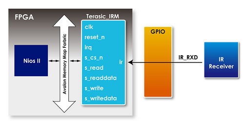
| - | Figure 1- is the block diagram of FPGA using TERASIC_IRM.v to decode IR control signal. The IR receiver receives signal and send the signal to this IP, this IP provides Avalon interface, a submodule irda_receive_terasic.v will do the decoding work. The decoded Custom Code and Key Code information will be sent to TERASIC_IRM. V and stored in the register. At the same time, an interrupt signal is sent to the CPU and the Nios CPU will read the key value that has just been decoded. The register format is shown as Table 1- : | + | Figure 1-28 is the block diagram of FPGA using TERASIC_IRM.v to decode IR control signal. The IR receiver receives signal and send the signal to this IP, this IP provides Avalon interface, a submodule irda_receive_terasic.v will do the decoding work. The decoded Custom Code and Key Code information will be sent to TERASIC_IRM. V and stored in the register. At the same time, an interrupt signal is sent to the CPU and the Nios CPU will read the key value that has just been decoded. The register format is shown as Table 1-8 : |
<div style="text-align:center;">[[Image: BAL_04_User_Guide_pic_49.png|500px]]</div> | <div style="text-align:center;">[[Image: BAL_04_User_Guide_pic_49.png|500px]]</div> | ||
| - | <div style="text-align:center;"> '''Figure 1- <span style="color:#333333;"> Block diagram of using TERASIC_IRM.v to decode IR signal '''</span></div> | + | <div style="text-align:center;"> '''Figure 1-28 <span style="color:#333333;"> Block diagram of using TERASIC_IRM.v to decode IR signal '''</span></div> |
| - | <div style="text-align:center;"> '''Table 1- Register Format'''</div> | + | <div style="text-align:center;"> '''Table 1-8 Register Format'''</div> |
| Line 1,681: | Line 1,679: | ||
| style="background-color:#979797;border:0.75pt solid #797979;padding:0.026cm;" | '''Description''' | | style="background-color:#979797;border:0.75pt solid #797979;padding:0.026cm;" | '''Description''' | ||
|- | |- | ||
| - | | style="background-color:#ffffff;border-top:0.75pt solid #cccccc;border-bottom: | + | | rowspan="3" style="background-color:#ffffff;border-top:0.75pt solid #cccccc;border-bottom:0.75pt solid #cccccc;border-left:0.75pt solid #cccccc;border-right:none;padding:0.026cm;" | Base Addr + 0 |
| Line 1,690: | Line 1,688: | ||
| style="background-color:#ffffff;border:0.75pt solid #cccccc;padding:0.026cm;" | Inversed Key Code | | style="background-color:#ffffff;border:0.75pt solid #cccccc;padding:0.026cm;" | Inversed Key Code | ||
|- | |- | ||
| - | | style="background-color:#ffffff;border-top:0.75pt solid #cccccc;border-bottom:0.75pt solid #cccccc;border-left:0.75pt solid #cccccc;border-right:none;padding:0. | + | | style="background-color:#ffffff;border-top:0.75pt solid #cccccc;border-bottom:0.75pt solid #cccccc;border-left:0.75pt solid #cccccc;border-right:none;padding:0.026cm;" | 24:16 |
| style="background-color:#ffffff;border-top:0.75pt solid #cccccc;border-bottom:0.75pt solid #cccccc;border-left:0.75pt solid #cccccc;border-right:none;padding:0.026cm;" | RO | | style="background-color:#ffffff;border-top:0.75pt solid #cccccc;border-bottom:0.75pt solid #cccccc;border-left:0.75pt solid #cccccc;border-right:none;padding:0.026cm;" | RO | ||
| style="background-color:#ffffff;border-top:0.75pt solid #cccccc;border-bottom:0.75pt solid #cccccc;border-left:0.75pt solid #cccccc;border-right:none;padding:0.026cm;" | Key Code | | style="background-color:#ffffff;border-top:0.75pt solid #cccccc;border-bottom:0.75pt solid #cccccc;border-left:0.75pt solid #cccccc;border-right:none;padding:0.026cm;" | Key Code | ||
| Line 1,827: | Line 1,825: | ||
<span style="color:#000080;">'''Getting Help'''</span> | <span style="color:#000080;">'''Getting Help'''</span> | ||
| - | Here is the contact information where you can get help if you encounter problems: | + | Here is the contact information where you can get help if you encounter problems: |
| - | + | *Terasic Inc.9F, No.176, Sec.2, Gongdao 5th Rd, East Dist, Hsinchu City, Taiwan 300-70 | |
| - | + | *Email : [mailto:support@terasic.com support@terasic.com] | |
| + | *Web : [http://www.terasic.com/ www.terasic.com] | ||
| Line 1,836: | Line 1,835: | ||
Revision History | Revision History | ||
| - | + | {|style="border-spacing:0;width:13.781cm;" | |
| - | {| | + | |
|- | |- | ||
| style="border-top:0.5pt solid #999999;border-bottom:0.5pt solid #999999;border-left:0.5pt solid #999999;border-right:none;padding:0cm;" | '''Date''' | | style="border-top:0.5pt solid #999999;border-bottom:0.5pt solid #999999;border-left:0.5pt solid #999999;border-right:none;padding:0cm;" | '''Date''' | ||
Latest revision as of 16:36, 17 July 2018
Contents |
Chpater1 Using the Self-Balancing Robot
1-1 Control the Motor
To keep the robot in vertical balance status, user need to control the rotation of the motor and make sure the accelerated rotation direction is reversed to the robot tilt direction. User need to learn how to control the rotation direction and speed of the motor.
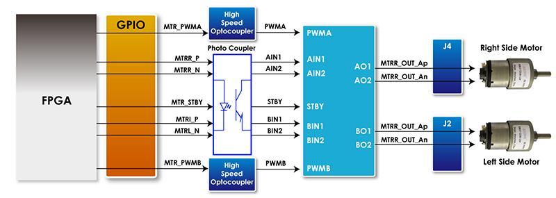
This section describes how to control the motor forward rotation or reverse, also describes how to control the speed of the motor. As general FPGA IOs of DE10-Nano are unable to drive the motor, an extra motor drive chip or circuit is needed to drive the motors, the motor drive chip used on the robot is Toshiba TB6612FNG, which can be used to control two DC motors simultaneously. As shown in Figure 1-1 , the control signals--- IN1, IN2, PWM (control signals of motor A and B) and STBY are connected to FPGA, the control signals --O1 and O2 output to the motor. The way to control the rotation direction and speed of the motors is described as below.
Note: As there are some photo couplers between the FPGA and TB6612FNG, the logic of control signals output from FPGA should be opposite to the logic described in the TB6612FNG datasheet.
- Control Rotation Direction
Table 1-1 lists the TB6612FNG control function.
| FPGA Control Output | Driver Input | Driver
Output
| Modes description | |||||||
| MTRX_P | MTRX_N | MTR_PWMX | MTRX_STBY | IN1 | IN2 | PWM | STBY | O1 | O2 | -- |
| 0 | 0 | 1/0 | 0 | 1 | 1 | 1/0 | 1 | 0 | 0 | Short brake |
| 1 | 0 | 1 | 0 | 0 | 1 | 1 | 1 | 0 | 1 | CCW |
| 0 | 0 | 0 | 1 | 0 | 0 | Short brake | ||||
| 0 | 1 | 1 | 0 | 1 | 0 | 1 | 1 | 1 | 0 | CW |
| 0 | 0 | 0 | 1 | 0 | 0 | Short brake | ||||
| 1 | 1 | 1 | 0 | 0 | 0 | 1 | 1 | OFF
(High Impedance) | Stop | |
| 0/1 | 0/1 | 1/0 | 1 | 1/0 | 1/0 | 1/0 | 0 | OFF
(High Impedance) | Standby | |
- Control the logic value for IN1 and IN2 can drive the motor to counterclockwise rotation (IN1 = 0; IN2 = 1) or clockwise rotation (IN1 = 1; IN2 = 0).
- The motor will stop rotation when logics of both the two control signals (IN1 and IN2) are 0.
- STBY is equal to Chip Enable function. The motor will stop and wait for new command when STBY logic is 0.
In summary, user can easily change the motor rotation direction via controlling the IN1 and IN2 logic value.
- Control Rotation Speed
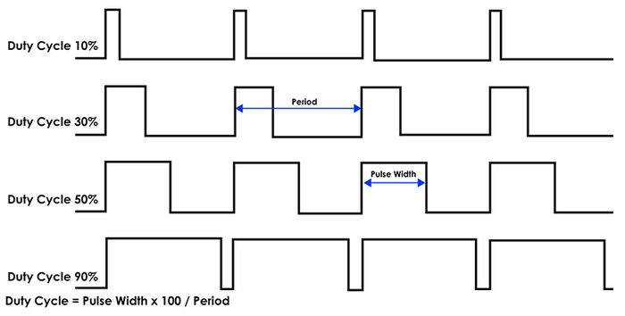
The motor speed of the motors can be controlled by controlling the Duty Cycle of the PWM signal. As shown in Figure 1-2 , the motor speed is faster while the PWM signal Duty Cycle is higher (Which means the ratio of the high logic positive pulse duration to the total pulse period is higher).
The maximum PWM frequency that TB6612FNG provides is 100KHz. For the Self-Balancing Robot, the PWM frequency is set as 7.14KHz.
- Example Description
Motor control IP TERASIC_DC_MOTOR_PWM.v is provided in the robot demo code. In this demo, it is packed as Qsys component and used to control the right and left motor. User can find the TERASIC_DC_MOTOR_PWM.v file in the robot system CD: Demonstrations\BAL_CAR_Nios_Code\IP\TERASIC_DC_MOTOR_PWM
- IP Symbol
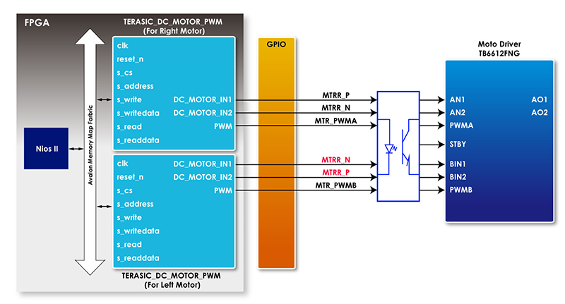
Figure 1-3 shows the symbol of TERASIC_DC_MOTOR_PWM.v and its block diagram. The main outputs are DC_MOTOR_IN1, DC_MOTOR_IN2 and PWM, others are Avalon interface signals. The DC_MOTOR_IN1 and DC_MOTOR_IN2 are the control signals that can control the motor rotation direction and stopping, which has been described in previous section. PWM control signal is responsible for controlling the motor speed.
Table 1-2 describes the Register Table of the motor control IP. Base Address 1~0 is the control register of PWM, Base Address 2 is the control register of motor brake control. User can read these registers value through Nios.
| Reg Address | Bit Field | Type | Name | Description |
| Base Addr + 0 | 31:0 | R/W | total_dur | PWM total duration value |
| Base Addr + 1 | 31:0 | R/W | high_dur | PWM high duration value |
| Base Addr + 2 | 31:3 | - | Unused | Unused bit |
| 2 | R/W | motor_fast_decay | Motor brake control 1 for fast brake0 for short brake | |
| 1 | R/W | motor_forward | Motor direction control : 1 for forward 0 for backward | |
| 0 | R/W | motor_go | Motor enable:1 for start 0 for stop |
- IP Code Description
Control Rotation Direction :
Below is Partial code for controlling the rotation direction:
always @(*)
begin
if (motor_fast_decay)
begin
// fast decay
if (motor_go)
begin
if (motor_forward)
{DC_MOTOR_IN2, DC_MOTOR_IN1,PWM} <= {1'b1, 1'b0,PWM_OUT}; // forward
else
{DC_MOTOR_IN2, DC_MOTOR_IN1,PWM} <= {1'b0, 1'b1,PWM_OUT}; // reverse
end
else
{DC_MOTOR_IN2, DC_MOTOR_IN1,PWM} <= {1'b1, 1'b1,1'b0};
end
else
begin
// slow decay
if (motor_go)
begin
if (motor_forward)
{DC_MOTOR_IN2, DC_MOTOR_IN1,PWM} <= {1'b1, 1'b0,PWM_OUT}; // forward
else
{DC_MOTOR_IN2, DC_MOTOR_IN1,PWM} <= {1'b0, 1'b1,PWM_OUT}; // reverse
end
else
{DC_MOTOR_IN2, DC_MOTOR_IN1,PWM} <= {1'b0, 1'b0,1'b0};
end
end
The register values of motor control register are related to DC_MOTOR_IN1 and DC_MOTOR_IN2 control signals, then user can control the motor rotation direction.
To drive the motors moving forward, user need set both motor_go and motor_forward as “1”. Then the code “"DC_MOTOR_IN2, DC_MOTOR_IN1, PWM} <= {1'b1, 1'b0, PWM_OUT}; // forward" will be executed.
DC_MOTOR_IN1 outputs logic 0 and DC_MOTOR_IN2 outputs logic 1. During the logic transmit from FPGA to motor driver IC, they will be inverted to 1 and 0 respectively through the photo coupler. IN1 and IN2 of TB6612FNG will receive logic 1 and 0 respectively. As shown in Table 4-1, in this state, the motor will be clockwise rotation to drive the robot moving forward.
User can set motor_fast_decay as 1 and motor_go as 0 if they need a fast braking. Then, the below code will be executed.
DC_MOTOR_IN2, DC_MOTOR_IN1, PWM} <= {1'b1, 1'b1,1'b0};
Finally, the IN1 and IN2 logic will receive logic 0 and logic 0 respectively. As shown in Table 4-1, the motor is stopped.
The right and left motors on the robot are assembled opposite, so their rotation direction is opposite too. As we use the same IP to control both the right and left motor, the control signals in project top level file ( DE10_Nano_Bal.v) are defined opposite, as described in code below:
Qsys u0 (
//clock && reset
.clk_clk (FPGA_CLK2_50), // clk.clk)
.reset_reset_n (1'b1), // reset.reset_n
//right motor control
.dc_motor_right_conduit_end_1_pwm (MTR_PWMA), // dc_motor_right_conduit_end_1.pwm
.dc_motor_right_conduit_end_1_motor_in1 (MTRR_P), // .motor_in1
.dc_motor_right_conduit_end_1_motor_in2 (MTRR_N), // .motor_in2
//left motor control
.dc_motor_left_conduit_end_1_pwm (MTR_PWMB), // dc_motor_left_conduit_end_1.pwm
.dc_motor_left_conduit_end_1_motor_in1 (MTRL_N), // .motor_in1
.dc_motor_left_conduit_end_1_motor_in2 (MTRL_P),
Control Rotation Speed :
Below is partial code for controlling the rotation speed:
////////////////////////////////////////
// PWM
reg PWM_OUT;
reg [31:0] total_dur;
reg [31:0] high_dur;
reg [31:0] tick;
always @ (posedge clk or negedge reset_n)
begin
if (~reset_n)
begin
tick <= 1;
end
else if (tick >= total_dur)
begin
tick <= 1;
end
else
tick <= tick + 1;
end
always @ (posedge clk)
begin
PWM_OUT <= (tick <= high_dur)?1'b1:1'b0;
end
The tick register is the main counter, total_dur represents the total_dur register described in Table 1-2. When the tick value equals to total_dur setting value, the whole counter will be reset and recounted. PWM_OUT represents one PWM cycle is finished. So, the longer the PWM cycle is, the larger the total_dur value will be. In this demo, the total_dur register is set to 7000 as default, it is one PWM cycle when the counter counts to 7000. The output PWM frequency is 7.14KHz (50MHz/7000).
As shown in Figure 1- , the motor speed depends on high_dur register. During one PWM cycle, when the tick value is less than high_dur, the PWM output is 1; otherwise, the PWM output is 0. So, the PWM Duty Cycle depends on the high_dur. Therefore, the larger the high_dur value is, the Duty Cycle will be larger and rotation speed will be faster.
1-2 Detect the Motor speed and Direction
Section 1.1 introduces how to control motor speed and direction, this section will introduce how to use the Hall effect sensor and decoder on the motor to detect the motor speed and direction in real time.
- Detection Principle
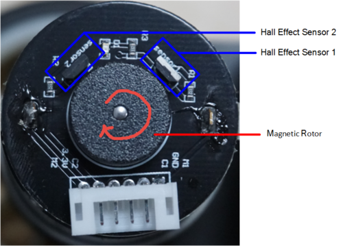
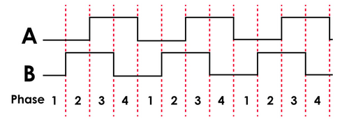
Figure 1-5 shows the appearance of motor, there are two Hall effect sensors and one magnetic Rotor on the motor. When the motor rotates, it will drive the magnetic Rotor to pass through the Hall effect sensors, and then, the Hall effect sensor magnetic force will change and generate Hall effect voltage, a digital circuit will process the Hall effect voltage and output square wave pulse (See Figure 1-6 ).
The two Hall effect sensors output two waves in different phases (Phase A and Phase B) as the two sensor locations are different (See Figure 1-5 ). When magnetic Rotor rotates, the first sensed sensor will output wave first, and the other sensor output will delay. That is why the two waves have different phases. So, we can know the motor rotation direction according which sensor wave phase is ahead. Figure 1-7 is the motor clockwise rotation status. In addition, we can also calculate the motor speed according to the pulse number. Over a period of time, the faster the motor rotates, the more pulses it generates.
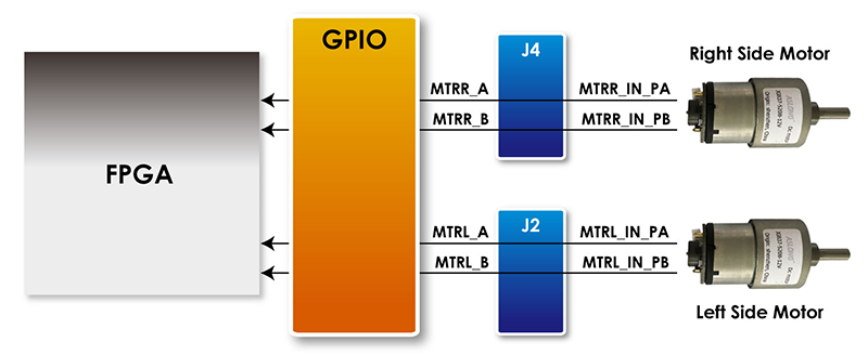
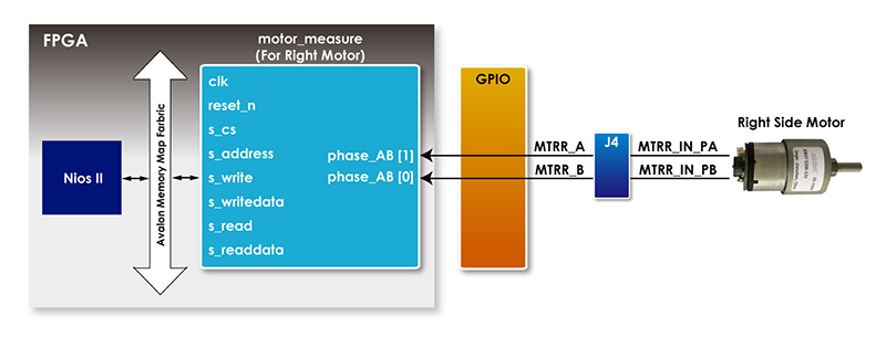
Figure 1-8 shows the motor phase pins connecting to FPGA. We can obtain the motor speed and direction in real time by writing code to just detect the phase and pulse number of the two signals (MTRR_IN_PA, MTRR_IN_PB).
- Example Description
We do provide a Qsys IP in the Self-Balancing Robot demo for users to obtain the motor speed and direction, the IP can be found in folder:
\Demonstrations\BAL_CAR_Nios_Code\IP\motor_measure\motor_measure.v
- IP Symbol
Figure 1-9 is the symbol and the system block diagram of motor_measure.v. Here we only draw the detecting diagram of the motor on the right, and the motor on the left also has the same module to detect the speed.
The module phase_AB[1:0] is used to connect the motor to receive the waves from the Hall effect sensor. The module can detect and obtain the motor speed and direction and save the data in the module register. CPU can read the data from Avalon bus.
- Register Table
Table 1-3 is the IP register table. The Counter register in address “Base Addr+0” will counts the motor pulse number. The system can detect how much the motor rotates according to this register, and the positive number means clockwise direction, the negative number means counterclockwise direction. Counter is read only register, the CPU can only read the Counter value. The Counter register in address “Base Addr+2” is for write. The count_en register in address “Base Addr+1” is for controlling the two Counters. When count_en is set to 1, the Counter register will start to count.
| Reg Address | Bit Filed | Type | Name | Description |
| Base Addr + 0 | 31:16 | RO | Unuse | - |
| 15:0 | RO | Counter (For Read) | Read Counter value for Motor output pules | |
| Base Addr + 1 | 31:30 | RW | Unuse | - |
| 1 | RW | count_en | Enable Motor pulse counter | |
| Base Addr + 2
| 31:16 | WO | Unused | - |
| 15:0 | WO | Couter (For Write) | Set Counter vaule |
- IP Code Description
There is a submodule code TERAISC_AB_DECODER.v in motor_measure.v IP, this submodule can detect phase A and phase B signals from the motor, and according the different phases, the submodule can figure out whether the rotation direction is clockwise or counterclockwise. The direction result will output to DO_DIRECT port and the rotation pulse will output to DO_PULSE port. Then these two signal will pass to the motor_measure.v IP.
TERAISC_AB_DECODER u_decoder
(
.DI_SYSCLK(clk),
.DI_PHASE_A(phase_AB[0]),
.DI_PHASE_B(phase_AB[1]),
.DO_PULSE(conter_pulse),
.DO_DIRECT(direction)
);
Please refer to below code list in below, the motor_measure IP has a 16bit Counter (initial value is 16'h8000) register, which is enabled only if the "count_en" register is set to 1. In the beging When the motor rotates clockwise (direction = 1), The Counter register will count from the initial value and increase by the number of pulses returned from the motor; If the motor rotates counterclockwise, the Counter register also will decrement with the number of pulses returned by the motor. The system will periodically read the value of this Counter register to acquire the current number of rotation speed of the motor.
always @( posedge clk)
begin
if(s_cs && s_write && s_address==`CNT_WRITE)
counter<=s_writedata[15:0];
else if(count_en && conter_pulse )
begin
if(direction)
begin
if(counter<16'hffff)
counter<=counter+1;
end
else if(!direction)
begin
if(counter>0)
counter<=counter-1;
end
else
counter<=0;
end
end
Users can refer to the Nios version demo file Motor.cpp (which location is \Demonstrations\BAL_CAR_Nios_Code\software\DE10_Nano_bal) for the steps of system reading counter. During the Self-Balancing Robot system initialization process, the count_en will be set to 1, after this, the system will read the counter every 10ms. Every time after the reading, the system will set the counter back to the initial value(16'h8000) and wait for the next reading time. The system will use the latest counter value to minus the initial value (16'h8000), the result will be a positive number if the motor direction is clockwise, the result will be a negative number if the motor direction is counterclockwise.
The counter values of the two motors will finally transfer to the balancing PID algorithm.
1-3 Get the tilt angle of Robot
This section describes how to obtain the tilt angle of the Self-Balancing Robot, and how to get an angularity correction to keep the robot balance.
- How to get the tilt angle of the body
The idealized state of the balance car is to maintain a vertical 90-degree angle to the ground. However, there are only two wheels support the body, which is more likely to lean forward or backward. It actually exists an angle of θ showing as Figure 1-10 . Our aim is to read out this angle and feed it back to the balance system for controlling the motor rotating in the opposite direction. In this way, it will make the tilt of the Angle to become the ideal 0 degree as a correction.
To obtain the tilt angle of the body, the Motion Tracking device MPU-6500 on the robot will be used. The single-chip MPU-6500 integrates a 3-axis accelerometer, and a 3-axis gyroscope. It is able to read out the acceleration of there-axis (/g) from accelerator, and angular velocity of three axes (/Sec) from the gyroscope. The balance system will use both of these two sensors to compute the tilt angle.
First of all, we need to obtain the status of the XYZ coordinates of the MPU-6500 in the robot. From Figure 1-11 , It can be seen if the balance of the car is tilted forward or backward, corresponding changes resulting the acceleration of the X-axis and Y-axis. Meanwhile, the angular velocity of the Y-axis will also change.
Continue to introduce how to calculate the tilt angle of the balance car from the accelerometer. Figure 1-2 , ignore the horizontal acceleration of the car, there is a vertical angle θ when body tilts forward or backward. G is for the acceleration of gravity. Resolve g vector into X and Z directions, gx and gz are coordinate components for X-axis and Z-axis respectively, θ is the tangent angle of gx or gz. Read out the values of gx & gz from the accelerometer in the MPU-6500. Get the degree of angle θ by using the function θ = arctan(gx/gz).
Besides, it can also get the body tilted angle from Y-axis angular rate by using the gyroscope in the MPU-6500. See below Figure 1-13 , when the body tilts, the angular rate changes as well. Obtain the angle in Y-axis via doing the integral calculation on the angular rate.
There is an error in the angles calculated by the above two methods. When the accelerometer reads the angle, the acquired value error will increase when the outside is disturbed. Use the gyroscope's angular velocity to integrate the acquired angle, due to the integral calculation will accumulate the error, and increase with time, the error will become bigger and bigger. If you use the angle with larger error to balance the system, it will be very difficult to stabilize the robot. Therefore, so a method on Angle error correction is required.
It is common to use Kalman Filter as a method, which adopts the data fusion of two sensors (gyro and accelerometer) to get a more precise angle.
Figure 1-14 shows the comparison of the original tilt Angle (blue) and the Angle (orange) by Kalman Filter. From the figure, you can see that the change in angle is large different for unfiltered angle (blue). By working with these data, the balance of the car body could not be stable. However, the varying amplitude for the orange Angle after filtering is significantly reduced.
- MPU-6500 Operation
FPGA uses I2C or SPI interface to control the MPU-6500, In our demo, we use the I2C interface to read the register of the MPU-6500 with Salve Address 7'b1011001. The data registers of XYZ axis accelerator and gyroscope locate in the range of 3B(Hex) ~ 48(Hex). It requires the initial operation on starting up. For more details about the MPU-6500 and Register map, please refer to the CD\Datasheet\Sensor\. And refer to the MPU.cpp & MPU.h provided in CD\Demonstrations\BAL_CAR_Nios_Code\software\DE10_Nano_bal\ for control code.
- Example Descriptions
We provide the Nios II demo for balance car by using the Open-core I2C module in Qsys. This module allows Nios II to access the mpu-6500 through the I2C interface.
The function for obtaining the tilted angle is provided in path: \Demonstrations\BAL_CAR_Nios_Code\software\DE10_Nano_bal\main.cpp, the main codes are as following:
/**************************************************************************
Function : Get Angle value (Kalman filter)
parameter :
return value :
**************************************************************************/
void Get_Angle(void)
{
int16_t ax, ay, az, gx, gy, gz;
mpu.getMotion6(&ax, &ay, &az, &gx, &gy, &gz);
Gyro_Balance=-gy;
x_angle=atan2(ax,az)*180/PI;
gy=gy/16.4;
Angle_Balance=kalman.getAngle(x_angle,-gy);
Gyro_Turn=gz;
}
First, read out the acceleration of X-, Y-, & Z- Axes and angular rate of gyroscope.
mpu.getMotion6(&ax, &ay, &az, &gx, &gy, &gz);
Because the polarity of the angular rate read out is opposite to the actual value, it is necessary to do a negative operation.
Gyro_Balance=-gy;
As described above, the tilted angle is obtained by computing the acceleration of X-axis & Y-axis. Use function atan2() to obtain the angle.
x_angle=atan2(ax,az)*180/PI;
As described above again, we can also get the tiled angle from Y- axis argular rate of gyroscope. However, the read-out value needs to divide by precision.
gy=gy/16.4;
Here, 16.4 is the Sensitivity Scale Factor for the gyroscope. Why use this value are introduced in the following descriptions.
The data register of the MPU-6500 is a 16-bit register, as the MSB is sign bit, the output range of the data register is -7FFF~7FFF, same as -32767~32767 in decimal format: See the diagram as below, if the full-scale range of ±2000 degrees/sec is selected, that means -32767 corresponding to -2000(°/s) and 32767 is corresponding to 2000(°/s). While reading out the value of gyroscope as 1000, the corresponding angular rate can be computed as below: 32767/2000 =1000/x; As x = 16.4(°/s),The corresponding Sensitivity Scale Factor is 16.4 LSB/(°/s) in the manual. It is able to compute the angular rate as the same way if selecting the other ranges.
Finally, send the Angle value obtained from the accelerometer and gyroscope the kalman filter function, to obtain the Angle of the car body with a smaller error.
Angle_Balance=kalman.getAngle(x_angle,-gy);
When dealing with the turning of the body, the system needs to refer to the angular velocity of the z axis.
Gyro_Turn=gz;
The parameters above will be provided to system for balance PID(Proportional–Integral–Derivative) controlling to feed back the actual condition of the body to achieve a balanced state.
1-4 Detect Obstacle Distance
This section describes how to detect the obstacle distance in front of the robot by using the Ultrasonic module.*
As shown in Figure 1-16 , the robot assembled HC-SR04 Ultrasonic module. Besides VCC and GND pin, the module is controlled mainly by TRIG and ECHO signal.
The detection process is described as below:* To start detecting the distance, input High-level logic signal to the TRIG I/O for at least 10us.
- The Module automatically sends eight 40 kHz and detect where there is pulse signal return.
- The echo port will automatically output a high-level logic when detecting a rebound signal. The duration of the high-level logic is the timing for the ultrasonic wave to be reflected back to the module after the ultrasonic wave is emitted from the module.
- Calculate Distance
Obstacle distance= (high level logic time × Velocity of sound (340m/s) / 2
The obstacle distance is calculated by the formula above, please note that the distance unit is meter.
- Demonstration Description
The demo provides Qsys IP which can read the obstacle distance from the Ultrasonic module, it’s located in \Demonstrations\BAL_CAR_Nios_Code\IP\sonic_distance\sonic_distance.v
- IP symbol
As shown in Figure 1-19 , the IP controls the TRIG pin, drives the module to start to detect obstacle, monitors whether there is reflection signal on ECHO pin and calculate the duration of the high level logic signal, then CPU will can read the data.
- Register Table
Table 1-4 shows the register table of the IP. measure_value register stores the ultrasonic transmission time that the module detects the obstacle distance each time.
| Reg Address | Bit Filed | Type | Name | Description |
| Base Addr + 0 | 31:22 | RO | Unuse | -- |
| 21:0 | RO | measure_value | Sonic wave propagation time |
- IP Code Description
The IP is consisted of a State Machine and below is the code:
always @(posedge av_mm_clk or negedge count_rst)
if(~count_rst)
begin
measure_count<=0;
trig_count<=0;
state<=0;
end
else
begin
case(state)
3'd0:begin
sonic_trigger<=1;
state<=1;
end
3'd1:begin
if(trig_count==2000)
begin
sonic_trigger<=0;
state<=2;
end
else
begin
trig_count<=trig_count+1;
state<=1;
end
end
3'd2:begin
if(!reg_echo&sonic_echo)
state<=3;
else
state<=2;
end
3'd3:begin
if(reg_echo&!sonic_echo)
state<=4;
else
begin
state<=3;
measure_count<=measure_count+1;
end
end
3'd4:begin
state<=state;
end
endcase
end
Figure 1-20 is the state diagram of the State Machine in the IP.
When the FPGA is running, this IP will operate independently and the state machine will go to State 0. The IP include a counter to avoid the State Machine blocks in a state, the counter will accumulate continually until 22'h3fffff then trigger count_rst=0, the State Machine will be reset. Below is the code:
always @(posedge av_mm_clk or negedge av_mm_rst)
if(~av_mm_rst)
counter<=0;
else if(counter==22'h3fffff)
counter<=0;
else counter<=counter+1;
wire count_rst=(counter==22'h3fffff)?0:1;
Below is the description for each state.
State 0: Set the output of TRIG pin to high level logic signal and the state machine goes to State 1.
State 1: In State 1, the counter trig_count starts to accumulate until counter achieves 2000. Since, the system clock is 50MHz. Thus, the accumulation time is 10us, so the request for pulling the TRIG to logic high for 10us is complete. Then, pulls the TRIG signal to low and goes to State 2.
State 2: Monitor whether the ECHO signal has rising edge state. If it has, the state machine goes to State 3, or the state machine is stay in State 2 until count_rst achieves 0, then the State machine is reset.
State 3: Calculate the ultrasonic reflection time by using the measure_count, the state machine goes to State 4 when ECHO pin signal has falling edge.
State 4: idle state, waiting for count_rst achieve 0, reset the state machine and begin to next detection.
- Software Code
After adding this IP to Qsys, Nios CPU can read the ultrasonic transmission and reflection time from measure_value register of the IP. Then calculate the obstacle distance by the formula, the Nios code in \Demonstrations\BAL_CAR_Nios_Code\software\DE10_Nano_bal\main.cpp is shown below and for designers’ reference:
data = IORD(SONIC_DISTANCE_0_BASE,0x00);
distance = (float)data*34.0/100000.0;
Note: As described in previous, the system clock in the IP is 50MHz and the distance unit is centimeter, apply to the formula, it is data * 340 * 100 / (2 * 50 * 1000000) = data*34.0/100000.
1-5 Balanced System
This section will introduce balancing system control of the self-balancing robot. This section describes how a robot can maintain its uprightness, speed, and state of turn and how it is controlled.
As described in the previous sections, the tilt-angle measurement and rotation-angle measurement of the robot are implemented by using the MPU-6500 to measure acceleration and gyroscope. The motor rotation speed of the robot is implemented by the Hall sensor of the motor. The obstacle avoidance function is implemented by the ultrasonic sensor measurement. These measured values are used as the feedback values for vertical control, rotation angle control and velocity control, respectively.
The status control of the robot introduces the concept of PID (Proportional–Integral–Derivative) controller, the robot uses PD ( Proportional Derivative) or PI ( Proportional Integral) to control the balancing status, which are used for vertical angle control, rotation angle control and velocity control, respectively. As these three controls are closed loop controls, they are also called as balance loop, turn loop and speed loop, respectively. The balance loop is controlled by PD controller, the velocity loop is controlled by PI controller, and the turn loop is controlled by PD controller.
The balance loop is controlled by PD controller, this is because the robot needs to respond quickly to the robot’s angle changing, and the derivative control just meets this requirement. The control value of P is tilt angle of the robot (the angle offset that is relative to balance status). The control value of D is the motor axial gyroscope. This loop corresponds to the int balance(float Angle,float Gyro) function in the software of our demo.
The speed loop is controlled by PI controller, which is the most commonly used control method for velocity control. PI controller is a linear control method. The deviation is formed according to the given value and the actual output value, then the Proportional (P) and Integral (I) of the deviation are composed of the control value by the linear combination, then the velocity can be controlled. The control value of P is velocity deviation, the control value of I is displacement. This loop corresponds to the int velocity (void) function in the software of our demo.
The turn loop is a simple control. In our demo, the turn value is measured by MPU-6500 Z-axis gyroscope and the difference of two speed encoders, which is used for D and P control value, respectively, so the rotation angle can be controlled by PD controller to ensure the angle keep the set value, and the response velocity of the robot can be improved by z-axis gyroscope control. This loop corresponds to the int turn(float Gyro) function in the software of our demo.
The block diagram of the three loops integrated function is shown in Figure 1-21 .
Note: The PID parameters of the balance loop, velocity loop and turn loop have polarity, so the feedback must be formed positive feedback to become the closed loop control which is advantageous to the robot balance.
The corresponding codes are Encoder_Integral=Encoder_Integral-Movement; in the int velocity(void) function and Bias+=110; and Bias-=110; in the int turn(float Gyro) function. When the Bluetooth and IR send control commands, the velocity loop and turn loop start working. The robot does a linear motion at a set speed, and rotates at a set angular speed.
The status of the robot needs to be sampling controlled at regular intervals. In our demo, the interval time is 10ms. The sampling control of the angle, velocity and rotation angle can be implemented by executing the interrupt function void MPU_INT_ISR(void * contex, alt_u32 id). Meanwhile, the while function in the main code is used for polling the Bluetooth/IR control signal, ultrasonic detection obstacle distance (for obstacle avoidance) signal and power monitoring signal.
The main routine flow chart is shown in Figure 1-22 .
1-6 Use the Bluetooth
This section introduces how to use the ESP32 module on the Self-balancing robot for Bluetooth connection. It enable the user to communicate the ESP32 with mobile phone via Bluetooth, and transfer the serial port protocol to FPGA for the moving control.
ESP32 is a powerful Bluetooth+WiFi module. It is easily developed. The Factory code in the ESP32 module has been written with ID Number of the Self-balancing robot, so it is able to accept the control command from mobile phone APP via Bluetooth connection. Besides it, there are also many other expandable functions such as I2C, WiFi and SPI data transmission, etc. However, in the robot, only the Bluetooth part is currently used, so only Bluetooth part is introduced.
- Example Descriptions
Figure 1-23 is for the system architecture of Self-balancing robot using the ESP32. When the ESP32 receives the string command from the app via the Bluetooth protocol, it will be transferred to the UART interface and pass to the UART IP of the QSYS within the FPGA. In this way, the NIOS CPU can easily read the value of the data register in the IP, and then compare it with the defined instruction to get an effective instruction and control the movement of the robot.
In the Quartus project of the demonstration, a PIO module is reserved in the Qsys system which is used for communicating the ESP32 module with FPGA I/O. It can be ignored as it not being used in the demo.
The UART IP is a Qsys built-in component, which user guide is available in:
<Quartus install path>\<Quartus version ex: 16.1 >\ip\altera\university_program\communication\altera_up_avalon_rs232\doc\ RS232.pdf.
The settings for the UART IP is as Figure 1-24 , Baud Rate set as115200.
As shown in Table 1-5 , the UART IP contains two registers: Data Register & Control Register. The read and write FIFOs are accessed via the data register. The Data transmitted via bluetooth will be stored here. RS232 UART Core’s interrupt generation and read-status information are controlled by the Control register.
| Offset in bytes | Register
Name | R/W | Bit description | ||||||||||||
| 31..24 | 23..16 | 15 | 14..11 | 10 | 9 | 8 | 7 | 6..2 | 1 | 0 | |||||
| 0 | data | RW | (1) | RAVAIL | RVALID | (1) | PE | (2) | (2) | DATA | |||||
| 4 | control | RW | (1) | WSPACE | (1) | WI | RI | (1) | WE | RE | |||||
Notes on Table 1-5
Table 1-6 shows the Data Register format, the bit 8~0 are for the data transferring, bit 23~16 are for indicating the number of characters remaining in the read FIFO. We can know the data transmission completed or not via bit 23~16.
| Bit number | Bit/Filed Name | Read/Write | Description |
| 8..0 | DATA | R/W | The value to transfer to/from the RS232 UART Core. When writing, the DATA field is a character to be written to the write FIFO. When reading, the DATA field is a character read from the read FIFO. |
| 9 | PE | R | Indicates whether the DATA field had a parity
error. |
| 15 | RVALID | R | Indicates whether the DATA and PE fields
contain valid data. |
| 23..16 | RVAIL | R | The number of characters remaining in the
read FIFO (including this read). |
The following will introduce how to use Nios to read the data transmitted by ESP32 and convert it to control commands. In the main.cpp (path:\BAL_CAR_Nios_Code\software\DE10_Nano_bal), the codes for Bluetooth controlling as below:
// Bluetooth control
temp=IORD(UART_BT_BASE,0x00);
number=temp>>16;
if(number!=0)
{
szData[i]=temp&0xff;
i++;
if((temp&0xff)==0x0a)
{
i=0;
if(CommandParsing(szData, &Command_EPS32, &Param)){
switch(Command_EPS32){
case CMD_FOWARD: //Forward
if(cmd_ut){
if(distance>15.0){
led3=0x01;
flag=0x01;
demo=false;
Car.Set_TurnFORWARD();
}}
else{
led3=0x01;
flag=0x00;
demo=false;
Car.Set_TurnFORWARD();
}
break;
case CMD_BACKWARD: //Backward
led3=0x02;
demo=false;
Car.Set_TurnBACKWARD();
break;
case CMD_LEFT: //Left
led3=0x04;
demo=false;
Car.Set_TurnLEFT();
break;
case CMD_RIGHT: //Right
led3=0x08;
demo=false;
Car.Set_TurnRIGHT();
break;
case CMD_STOP: //Stop
led3=0x00;
demo=false;
Car.Pause();
break;
First, read the receiving data register (Receiving data register offset address is 0)
temp=IORD(UART_BT_BASE,0x00);
The data width for receiving data register is 32 bits. However, when the command comes from the Bluetooth, the UART IP only transmit the 8 bits data at one time, so the full instruction needs to be received multiple times. You can know how many characters have not yet been read via checking the register data bit 23~16,
number=temp>>16;
If the read data number is not 0, that is, the data is valid. Take the last 8 bits into the array, and then receive the next 8 bits cyclically, when the received data is 0x0a (which is defined as end of transmission character). When transferring a control command completed on the mobile app, it will send out this value for data sending finished, Next to the command comparision, all commands from the bluetooth are definded in the command.h.
/*
* Command.h
*
*/
#ifndef COMMAND_H_
#define COMMAND_H_
#include "terasic_includes.h"
typedef enum{
}COMMAND_ID;
typedef struct{
char szCommand[10];
int CommandId;
bool bParameter;
}COMMAND_INFO;
COMMAND_INFO gCommandList[] = {
{"ATFW", CMD_FOWARD, false},
{"ATBW", CMD_BACKWARD, false},
{"ATTL", CMD_LEFT, false},
{"ATTR", CMD_RIGHT, false},
{"ATST", CMD_STOP, false},
{"ATAB", CMD_AKBT, false},
{"ATDM", CMD_ATDM, false},
{"ATUTON", CMD_ATUTON, false},
{"ATUTOFF", CMD_ATUTOFF, false},
};
#endif /* COMMAND_H_ */
Compare the command character from ESP32 with the definition in the command.h, it is able to parse the command. The source codes in main.cpp are as below:
/**************************************************************************
Function : Bluetooth Command Parsing
bool CommandParsing(char *pCommand, int *pCommandID, int *pParam){
bool bFind = false;
int nNum, i, j , x=0;
bool find_equal = false;
char Data[10]={0};
nNum
sizeof(gCommandList)/sizeof(gCommandList[0]);
for(i=0;i<nNum && !bFind;i++){
if (strncmp(pCommand, gCommandList[i].szCommand, strlen(gCommandList[i].szCommand)) == 0){
*pCommandID = gCommandList[i].CommandId;
if (gCommandList[i].bParameter){
//*pParam = 10; //??
//for(j=0;pCommand[j]!=0x0a;j++){
for(j=0;pCommand[j]!=0x0d;j++){
if(find_equal==true){
Data[x] = pCommand[j];
x++;
}
else if(pCommand[j]=='=')
find_equal=true;
}
*pParam=atoi(Data);
}
bFind = true;
} // if
} // for
return bFind;
}
Finally, the control command is converted to the corresponding function for the Self-balancing robot controlling. For example, the "Backward" command processing in below:
case CMD_BACKWARD: //Backward
led3=0x02;
demo=false;
Car.Set_TurnBACKWARD();
break;
1-7 Using the IR Controller
In addition to using the mobile phone app to control the robot via the Bluetooth, using an infrared remote control is also a simple and convenient option.
The infrared remote controller included with the kit package is an infrared remote controller that uses the NEC protocol. It uses 38K HZ frequency modulation to emit control signals to the infrared receiver on the robot. The FPGA decoder IP will decode the signal to control the robot motion.
- Infrared Remote Controller Protocols
The NEC format composes of a Leader Code, a 16-bit Custom Code, and a 8-bit Key Code. The Leader Code is transmitted first, which contains 9ms carrier frequency and 4.5ms zero signal, then followed by 16-bit Client Code, 8-bit Key Code and 8-bit Inversed Key Code, which is the reverse value of the Key Code, the robot IR receiver can use the Inversed Key Code to verify the Key Code.
The logic is judged through different time lengths, 560us carrier frequency plus 1690us 0 signal represents the transmission of logic 1, 560us carrier frequency plus 560us 0 signal represents logic 0.
The IR receiver on the balanced car can decode the carrier frequency of 38 kHz and reverse the received signal. Therefore, it should be noted that the signal processed in the FPGA will be opposite to that of the transmitter, as shown in Figure 1-25 .
- Self-Balancing Robot motion key definition and Key Code
See Figure 1- for IR controller’s function and key and its corresponding Inversed Key Code, Key Code and Custom Code are shown in Table 1-7.
- Example Descriptions
We provide an IR control decoder IP in the Self-Balancing Robot demonstrations folder, which location is \Demonstrations\BAL_CAR_Nios_Code\IP\TERASIC_IRM\TERASIC_IRM.v.
Figure 1-28 is the block diagram of FPGA using TERASIC_IRM.v to decode IR control signal. The IR receiver receives signal and send the signal to this IP, this IP provides Avalon interface, a submodule irda_receive_terasic.v will do the decoding work. The decoded Custom Code and Key Code information will be sent to TERASIC_IRM. V and stored in the register. At the same time, an interrupt signal is sent to the CPU and the Nios CPU will read the key value that has just been decoded. The register format is shown as Table 1-8 :
| Reg Address | Bit Filed | Type | Name | Description |
| Base Addr + 0
| 31:24 | RO | Inversed Key Code | Inversed Key Code |
| 24:16 | RO | Key Code | Key Code | |
| 15:0 | RO | Custom Code | Custom Code: 16'h6b86 |
If pressing IR controller key “2”, the register value will be 32'hfd026b86, the "6b86" is Custom Code, the "02" is Key Code, the “fd” is Inversed Key Code, which is the reversed value of “02”. After the Nios CPU receives IR interrupt signal, the Nios CPU will read the register value and compare it with the defined code table, and then, judge the meaning of the instruction. IR controller key codes(32bits) are defined in the file IrRx.h, as followed code lines:
typedef enum{
IR_POWER = 0xed126b86,
IR_CH_UP = 0xe51a6b86,
IR_CH_DOWN = 0xe11e6b86,
IR_VOL_UP = 0xe41b6b86,
IR_VOL_DOWN = 0xe01f6b86,
IR_MUTE = 0xf30c6b86,
IR_ADJ_LEFT = 0xeb146b86,
IR_ADJ_RIGHT = 0xe7186b86,
IR_PLAY_PAUSE = 0xe9166b86,
IR_NUM_0 = 0xff006b86,
IR_NUM_1 = 0xfe016b86,
IR_NUM_2 = 0xfd026b86,
IR_NUM_3 = 0xfc036b86,
IR_NUM_4 = 0xfb046b86,
IR_NUM_5 = 0xfa056b86,
IR_NUM_6 = 0xf9066b86,
IR_NUM_7 = 0xf8076b86,
IR_NUM_8 = 0xf7086b86,
IR_NUM_9 = 0xf6096b86,
IR_NUM_A = 0xf00f6b86,
IR_NUM_B = 0xec136b86,
IR_NUM_C = 0xef106b86,
IR_RETURN = 0xe8176b86,
IR_MENU = 0xee116b86
In main.cpp file, there are code lines for detecting IR:
// IR Remote control
if (!IR.IsEmpty()){
//Command_IR = IORD(IR_RX_BASE,0x00);
//printf("0000h\r\n", Command_IR);
switch(Command_IR){
case CIrRx::IR_NUM_5: //Stop
demo=false;
break;
case CIrRx::IR_NUM_2: //Forward
if(mode==0x02){
if(distance>15.0){
demo=false;
else{
demo=false;
break;
Using IR.IsEmpty to detect whether IR data is received or not, using IR.Pop to read register DATA_BUF value, and compare it with the defined code table, and then, judge the meaning of the instruction and control the Self-Balancing Robot moving forward or backward.
Chpater2 Additional Information
Getting Help
Here is the contact information where you can get help if you encounter problems:
- Terasic Inc.9F, No.176, Sec.2, Gongdao 5th Rd, East Dist, Hsinchu City, Taiwan 300-70
- Email : support@terasic.com
- Web : www.terasic.com
Revision History
| Date | Version | Changes |
| 2018.03.16 | First publication | |
