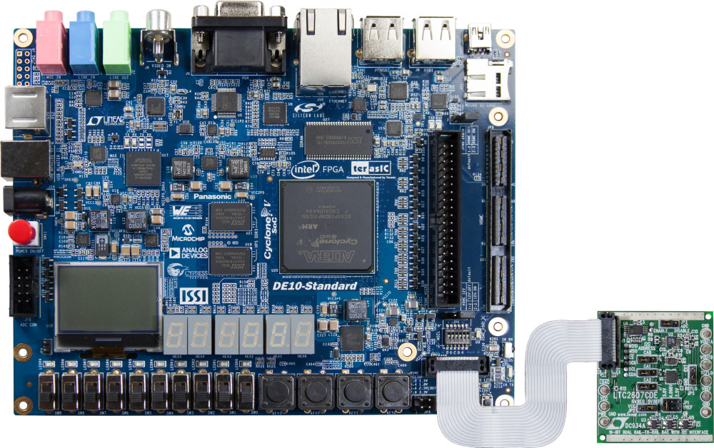
The DE10-Standard board has many features that allow users to implement a wide range of designed circuits, from simple circuits to various multimedia projects.
The following hardware is provided on the board:
FPGA Device
- Cyclone V SX SoC—5CSXFC6D6F31C6N
- 110K LEs, 41509 ALMs
- 5,761 Kbits embedded memory
- 6 FPGA PLLs and 3 HPS PLLs
- 2 Hard Memory Controllers
ARM-Based Hard Processor System (HPS)
- 925 MHz, Dual-Core ARM Cortex-A9 MPCore Processor
- 512 KB of Shared L2 Cache
- 64 KB of Scratch RAM
- Multiport SDRAM Controller with Support for DDR2, DDR3, LPDDR1, and LPDDR2
- 8-Channel Direct Memory Access (DMA) Controller
Configuration and Debug
- Serial Configuration Device – EPCS128 on FPGA
- On-Board USB Blaster II (Normal Type B USB Connector)
Memory Device
Communication
- Two USB 2.0 Host Ports (ULPI Interface with USB Type A Connector) on HPS
- USB to UART (Micro USB Type B Connector) on HPS
- 10/100/1000 Ethernet on HPS
- PS/2 Mouse/Keyboard
- IR Emitter/Receiver
Connectors
- One 40-pin Expansion Header (Voltage Levels: 3.3V)
- One HSMC Connector(Configurable I/O Standards 1.5/1.8/2.5/3.3V)
- One 10-Pin ADC Input Header
- One LTC Connector (One Serial Peripheral Interface (SPI) Master ,One I2C and One GPIO Interface ) on HPS
Display
- 24-bit VGA DAC
- 128x64 Dots LCD Module with Backlight on HPS
Audio
- 24-bit CODEC, Line-in, Line-out, and Microphone-In Jacks
Video Input
- TV Decoder (NTSC/PAL/SECAM) and TV-In Connector
ADC
- Sample Rate: 500 KSPS
- Channel Number: 8
- Resolution: 12 bits
- Analog Input Range : 0 ~ 4.096 V
Switches, Buttons and Indicators
- 5 User Keys (FPGA x4, HPS x1)
- 10 User Switches (FPGA x10)
- 11 User LEDs (FPGA x10 ; HPS x 1)
- 2 HPS Reset Buttons (HPS_RST_n and HPS_WARM_RST_n)7-Segment Display x6
Sensors
- G-Sensor on HPS
Power
- 12V DC Input
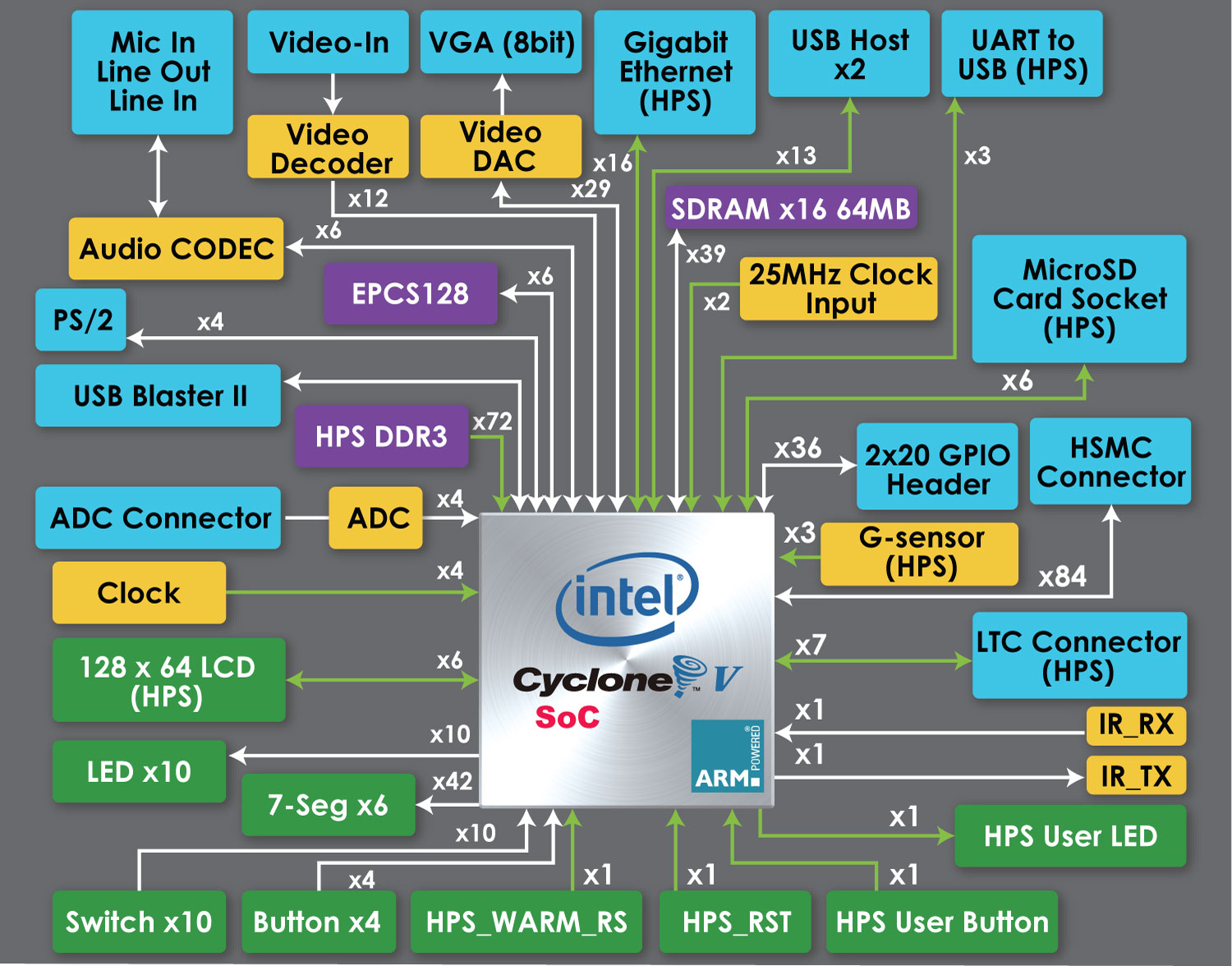
Block Diagram of the DE10-Standard Board
Connectivity
-
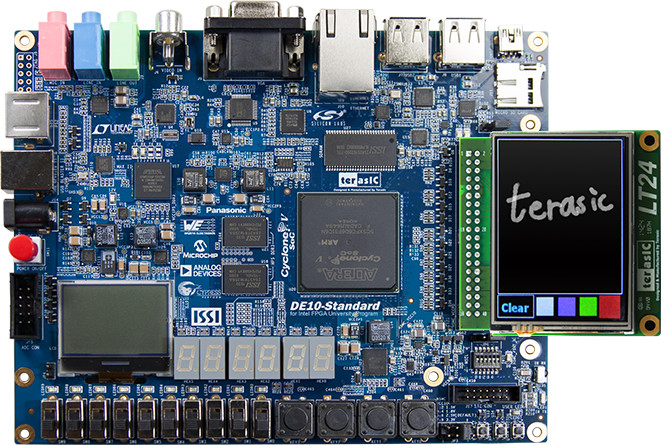
Connect LT24
-
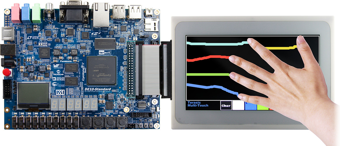
Connect MTL2
-
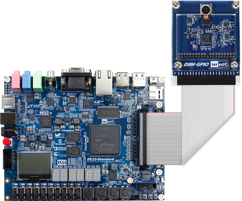
Connect D8M
-
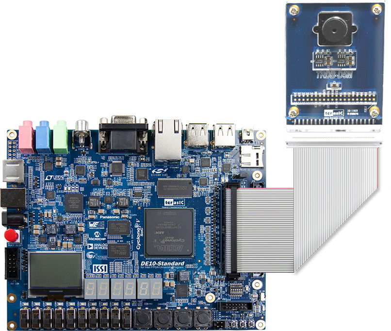
Connect D5M
-
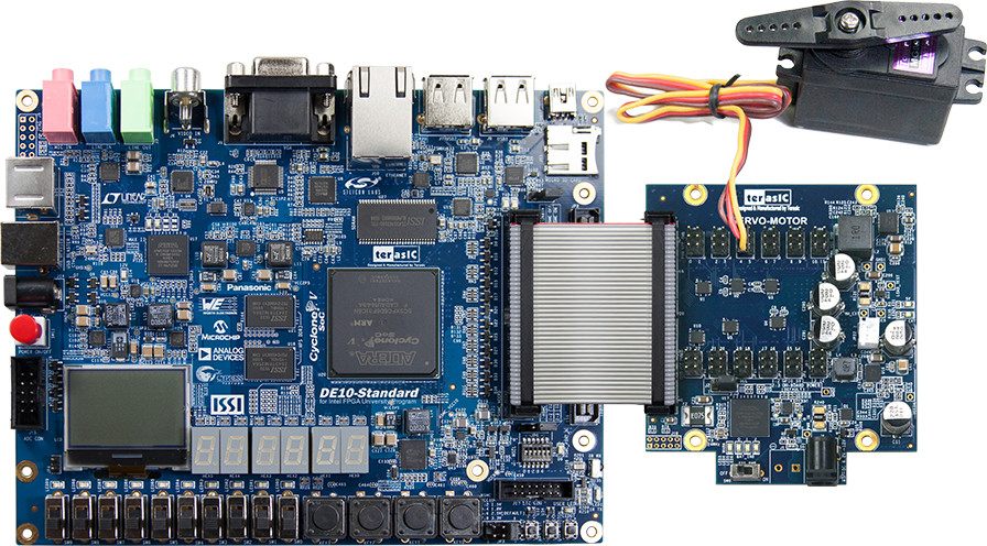
Connect SMK
-
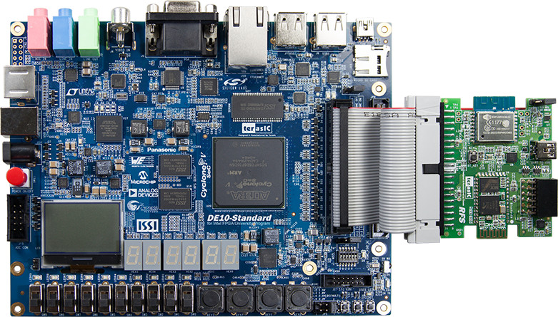
Connect RFS
-
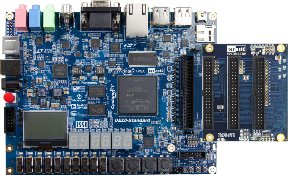
Connect HTG
-
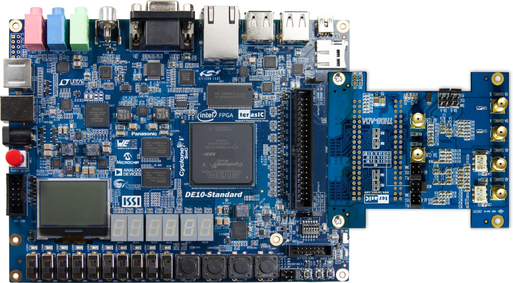
Connect ADA
-
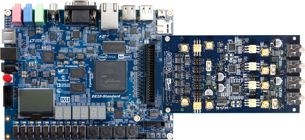
Connect DCC
-
Connect LTC2607 (AD/DA Daugher Card)
