DE10-Advance Hardware Manual revC Chapter2 Layout and Components
From Terasic Wiki
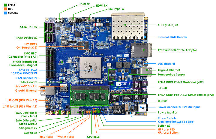
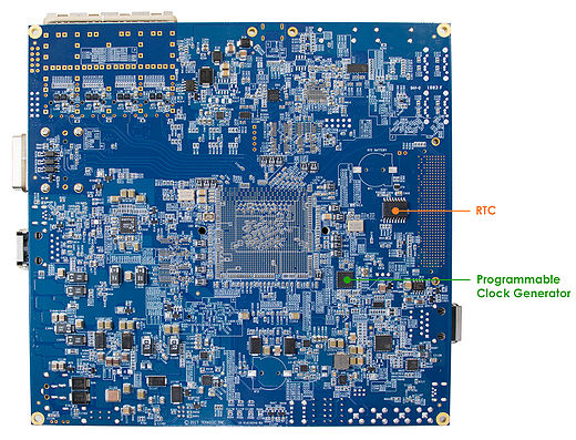
Figure 2-1 and Figure 2-2 shows a photograph of the board. It depicts the layout of the board and indicates the location of the connectors and key components.
- Figure 2-1 DE10-Advanced development board (top view)
- Figure 2-2 DE10-Advanced development board (bottom view)
The DE10-Advanced board has many features that allow users to implement a wide range of designed circuits, from simple circuits to various multimedia projects.
The following hardwares are provided on the board:
- FPGA Device
- Intel ® Arria10® SoC 10AS066K3F40E2SG device (660K LEs)
- USB-Blaster II onboard for programming; JTAG Mode
- Serial configuration device – EPCQL1024
- One DDR4 SO-DIMM Socket, support ECC
- On-board 1GB DDR4-2400, 32-bit data width
- USB Type-C Interface
- Power Delivery
- DisplayPort TX/RX with 4 lanes
- USB 3.0/2.0
- HDMI TX/RX 2.0 for 4K2K@60- FPGA Transceiver
- PCIe Cabling Socket at Gen3 x4
- SFP+ Socket x4, 40Gbps
- SATA 3.0 Host and SATA Device x2 (SATA Connector x4)
- One Gigabit Ethernet Port
- SMA Clock-In and Clock-Out
- High Pin Count FMC Connector. Support VADJ 1.2V/1.5V/1.8V.
- Accelerometer, Gyroscope and Magnetometer
- Temperature Sensor
- Fan Control
- LED x2, KEY x2, Switch x2, 7-Segment x2
- HPS (Hard Processor System)
- 1.5GHz Dual-core ARM Cortex-A9 processor
- Boost Flash Slot:
- 1024 Mb QSPI Flash
- Nand Flash
- MicroSD Socket
- On-board 1GB DDR4-2400, 32-bit data width
- 1 Gigabit Ethernet PHY with RJ45 connector
- USB OTG Port, USB mini-AB connector
- UART to USB, USB Mini-B connector
- RTC
- One user button and one user LED
- Warm reset button and cold reset button

