DE10-Advance Hardware Manual revC Chapter3 Board Setting Headers
From Terasic Wiki
Contents |
3.2 Board Setting Headers
JTAG Interface Header
J17 is the header used to set the JTAG bus of FMC connector connect to JTAG interface of DE10-Advanced system.The FMC connector will not be included in the JTAG chain if the headers are set to open(See Figure 3-3). Table 3-2 list the setting of the J17 header.
- Table 3-2 JTAG Interface Headers Setting
Header Setting Descriptions J17 Open (Default Setting) Disable the JTAG interface of the FMC connector into the JTAG chain

- Figure 3-3 The FMC Jtag Header
FMC_VCCIO Select Header
JP2 is used to set the VCCIO voltage of FPGA I/O on FMC connector, as1.2V/1.5V/1.8V are supported, the FMC connector can support various I/0 standard FMC daughtercards. Table 3-3 list the FMC_VCCIO Headers Setting.
- Table 3-3 FMC_VCCIO Headers Setting
JP2 Setting FMC VCCIO Voltage 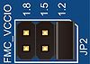
1.2V 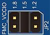
1.5V 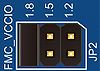
1.8V(Default Setting)


- Figure 3-4 The FMC VCCIO select header
PMODE Select Header
The USB 3.0 Controller (Cypress FX3) on the DE10-Advanced can be booted from a different sources, selected by the configuration of the PMODE header(JP4/JP5/JP6) on DE10-Advanced. Table 3-4 shows the boot options and associated settings. The default boot device is the from an serial flash via SPI interface.
- Table 3-4 PMODE Headers Setting
PMODE[2:0](JP6/JP5/JP4) Setting Boot Source F00 Sync ADMux (16-bit) F01 Async ADMux (16-bit) F11 USB boot F0F Async SRAM (16-bit) F1F I2C, On Failure, USB Boot is Enabled 1FF I2C only 0F1(Defualt) SPI, On Failure, USB Boot is Enabled
- F indicates Floating

- Figure 3-5 The PMODE select header