DE10-Advance Hardware Manual revC Chapter5 UART to USB
From Terasic Wiki
5.3 UART to USB
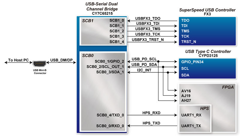
An USB to Serial device (Cypress: CY7C65215) is used on the DE10-Advanced to connect to other on-baord devices through JTAG / UART / I2C interface. Let Host PC can communicate with these devices through the USB interface(See Figure 1-1).
There are two serial communication blocks (SCB) in CY7C652152, in which SCB0 is used to connect HPS UART channel or USB PD controller (CYPD3125) I2C bus. The default setting is preset to HPS UART function, so HPS UART can communicates with Host PC vis this channel . Another option is the USB TypeC controller's I2C bus. This is reserved for the user to configure the firmware of the USB TypeC controller function from the Host PC. The channel is also connected to the FPGA at the same time, so that the FPGA can read the registers in the USB TypeC controller to monitor the state. If user wants to change the SCB0 to I2C, it needs to be modified from the setting software on the host PC.
The other channel of the CY7C65215 SCB1 is used as the JTAG interface, which is connected to the USB FX3 device, allowing the user to debug the FX3 chip via the JTAG interface through the Host PC software. Table 1-1 lists the pin assignment of USB to serial device connected to the FPGA'.

- Figure 1-1 Connections between the HPS and USB Mini-B connector
- Table 5-4 Pin Assignment of UART Interface
Signal Name FPGA Pin Number Description I/O Standard USB_PD_SCL PIN_AJ19 I2C Serial Clock VCCIO_FMC USB_PD_SDA PIN_AV16 I2C Serial Data VCCIO_FMC I2C_INT PIN_AH27 inter-integrated circuit 1.8V HPS_RXD_M PIN_L20 HPS UART Receiver 1.8V HPS_TXD_M PIN_J19 HPS UART Transmitter 1.8V