DE10-Advance Hardware Manual revD Chapter4 HDMI Transmitter and Receiver
From Terasic Wiki
4.7 HDMI Transmitter and Receiver
The DE10-Advanced board features HDMI transmitter and receiver. For HDMI transmitter,as shown in Figure 4-13. The board features a Transition Minimized Differential Signal(TMDS) retimer IC (TI:SN75DP159). Users can implement Intel or third-party IP in FPGA, HDMI video or audio data is encoded to TMDS signal and output from FPGA transceiver. The signals transmit to the retimer IC and display on HDMI monitor through HDMI connector. For HDMI Receiver, it features a Redriver IC(DIDOES:PI3HDX1204B1). It transmits the input TMDS signal into FPGA, and decoded to image video datas by Intel or third-party IP, then will be processed next step.
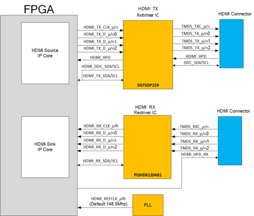
- Figure 4-13 The HDMI transceiver interface of the DE10-Advanced
- Table 4-11 HDMI TX and RX port Pin Assignments, Signal Names and Functions

Signal Name FPGA Pin Number Description I/O Standard HDMI_TX_CLK_p V39 TX TMDS clock channel HSSI Differential I/O HDMI_TX_D_p[0] U37 TX TMDS data channel 0 HSSI Differential I/O HDMI_TX_D_p[1] T39 TX TMDS data channel 1 HSSI Differential I/O HDMI_TX_D_p[2] R37 TX TMDS data channel 2 HSSI Differential I/O HDMI_TX_SCL A25 I2C clock of the TX retimer IC and DCC 1.8V HDMI_TX_SDA B25 I2C data of the TX retimer IC and DCC 1.8V HDMI_HPD AF28 TX Hot Plug Detect 1.8V HDMI_RX_CLK_p Y31 RX TMDS clock channel HSSI Differential I/O HDMI_RX_D_p[0] Y35 RX TMDS data channel 0 HSSI Differential I/O HDMI_RX_D_p[1] W37 RX TMDS data channel 1 HSSI Differential I/O HDMI_RX_D_p[2] W33 RX TMDS data channel 2 HSSI Differential I/O HDMI_RX_SCL V7 I2C clock of the RX redriver IC 1.2 V HDMI_RX_SDA T2 I2C clock of the RX redriver IC 1.2 V HDMI_HPD_RX AG27 RX Hot Plug Detect 1.8V HDMI_RX_5V_N B26 Detect if the TX terminal has 5V output 1.8V HDMI_REFCLK_p V31 HDMI Reference clock from on board PLL LVDS