TSoM Programming the EPCS Device revA
From Terasic Wiki
This guide describes how to program the serial configuration (EPCS) device with Serial Flash Loader (SFL) function via the JTAG interface. Users can program EPCS devices with a JTAG indirect configuration (.jic) file, which is converted from a user-specified SRAM object file (.sof) in Quartus. The .sof file is generated after the project compilation is successful. The steps of converting .sof to .jic in Quartus II are listed below.
Contents |
1.1 Before Programming Begins
The FPGA should be set to AS x1 mode i.e. MSEL[4..0] = “10010” to use the Flash as a FPGA configuration device. Note that the factory default mode is FPPx32 mode(MSEL[4:0]= "01010").
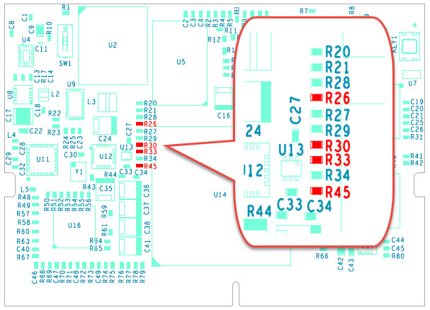
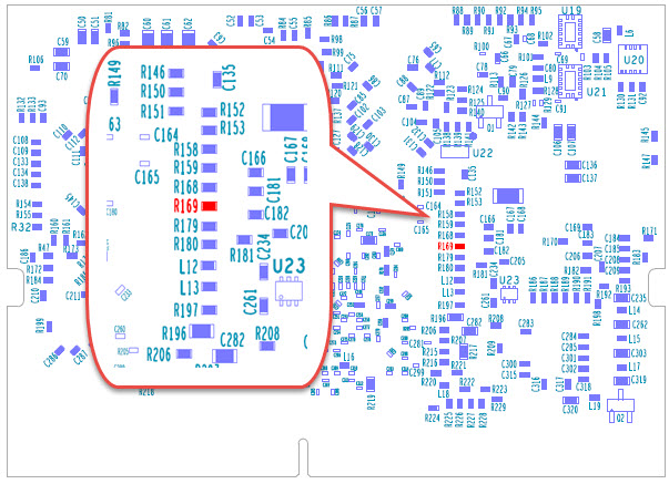
Please make sure the resistors in the red resistor position are installed in the figure below.
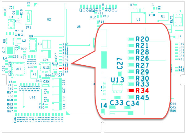
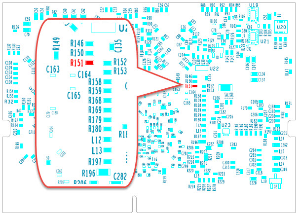
confirm that the red resistor position in the figure below DOES NOT have any resistors installed.
1.2 Convert .SOF File to .JIC File
To programme the design file into the EPCS device, a .jic file is required. Here's how to convert the .sof file generated by Quartus compile to .jic.
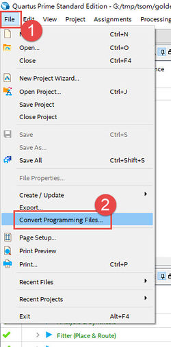
- Choose Convert Programming Files from the File menu of Quartus II.
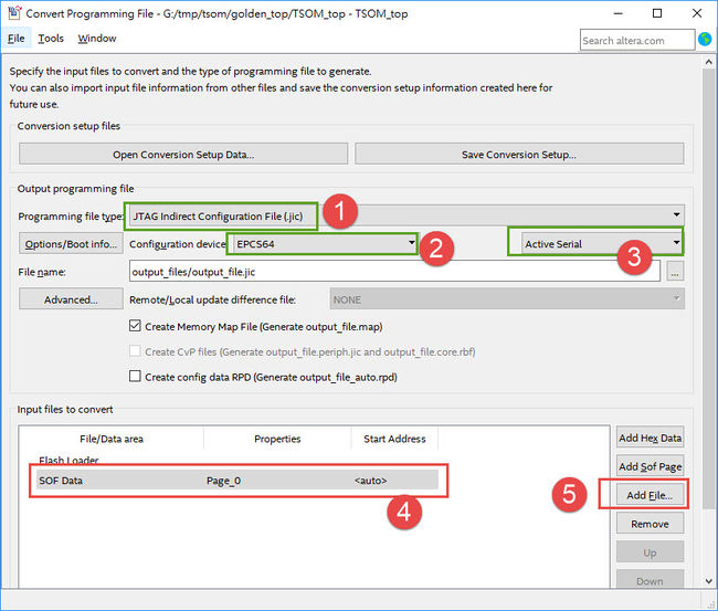
- Select JTAG Indirect Configuration File (.jic) from the Programming file type field in the dialog of Convert Programming Files.
- Choose EPCS64 from the Configuration device field.
- Choose Active Serial from the Mode filed.
- Browse to the target directory from the File name field and specify the name of output file.
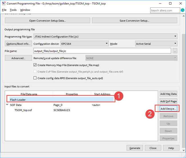
- Click on the SOF data in the section of Input files to convert.
- Click Add File.
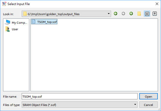
- Select the .sof to be converted to a .jic file from the Open File dialog.
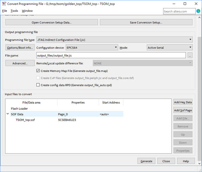
- Click Open and the Convert Programming Files page will appear.
- Click on the Flash Loader and click Add Device.
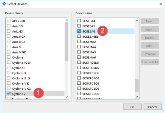
- The Select Devices page will appear, please select the targeted FPGA to be programed into the EPCS.
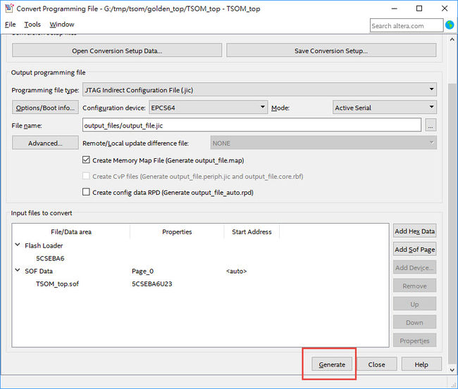
- Click OK and the Convert Programming Files page will appear.
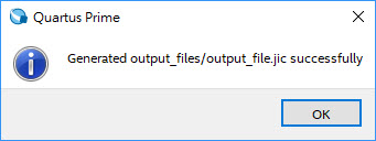
- Click Generate and wait the .jic file is generated.
1.3 Write JIC File into the EPCS Device
- Make sure the MSEL[4..0] is set to “10010” in AS mode.
- Choose Programmer from the Tools menu and the Chain.cdf window will appear.
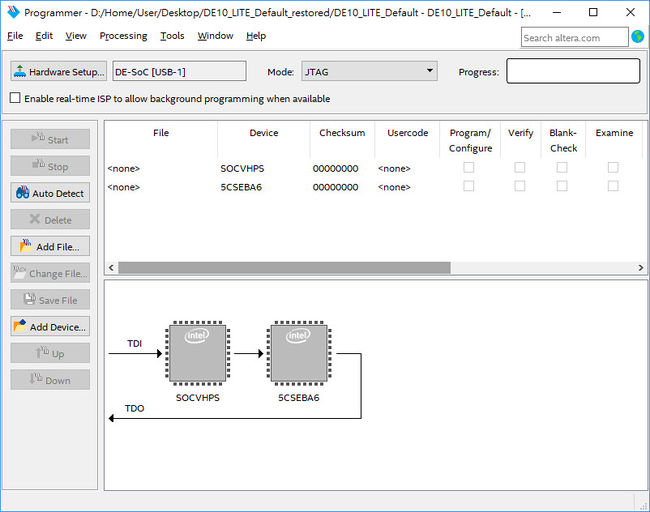
- Click Auto Detect and then select the correct device (5CSEBA6). Both FPGA device and HPS should be detected
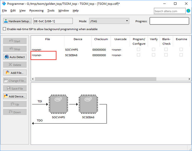
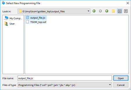
- Double click the red rectangle region shown in below and the "Select New Programming File" page will appear. Select the .jic file to be programmed.
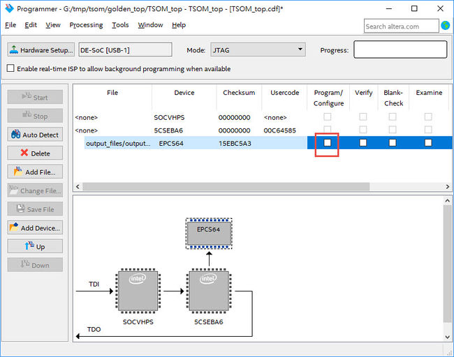
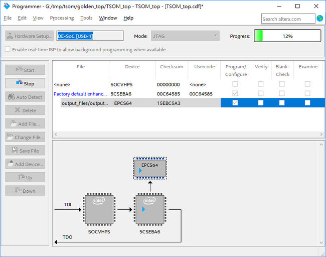
- Program the EPCS device by clicking the corresponding Program/Configure box. A factory default SFL image will be loaded.
- Click Start to program the EPCS device.
1.4 Erase the EPCS Device
- Make sure the MSEL[4..0] is set to “10010” in AS mode.
- Choose Programmer from the Tools menu and the Chain.cdf window will appear.
- Click Auto Detect, and then select correct device, both FPGA device and HPS will detected.
- Double click the red rectangle region shown in below, and the Select New Programming File page will appear. Select the correct .jic file.
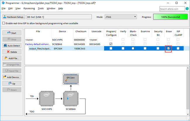
- Erase the EPCS device by clicking the corresponding Erase box. A factory default SFL image will be loaded.
- Click Start to erase the EPCS device.
