DE10-Advance Hardware Manual revC Chapter4 PCIe
From Terasic Wiki
4.6 DDR4
The board supports 1GB of DDR4 SDRAM comprising of two x32bit DDR4 devices on FPGA side. The DDR4 signals are connected to the vertical I/O banks on the bottom edge of the FPGA. The DDR4 devices shipped with this board are running at 1067 MHz, for a total theoretical bandwidth of over 66Gbps. Figure 4-8 shows the connections between the DDR4 and Arria 10 SoC FPGA. Table 4-9 lists the pin assignments of DDR4 and its description with I/O standard.
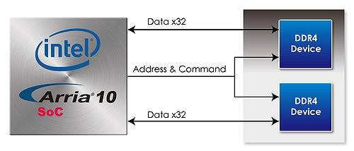
- Figure 4-8 The connection between DDR4 and Arria 10 SoC FPGA
- Table 4-9 The pin assignments of DDR4 component and its description with I/O standard
FPGA Pin Number Signal Name Description I/O Standard PIN_AU7 DDR4B_REFCLK_p DDR4 A port Reference Clock p LVDS PIN_AJ11 DDR4B_A[0] Address [0] SSTL-12 PIN_AH12 DDR4B_A[1] Address [1] SSTL-12 PIN_AP11 DDR4B_A[2] Address [2] SSTL-12 PIN_AN11 DDR4B_A[3] Address [3] SSTL-12 PIN_AM10 DDR4B_A[4] Address [4] SSTL-12 PIN_AM11 DDR4B_A[5] Address [5] SSTL-12 PIN_AP9 DDR4B_A[6] Address [6] SSTL-12 PIN_AN9 DDR4B_A[7] Address [7] SSTL-12 PIN_AR10 DDR4B_A[8] Address [8] SSTL-12 PIN_AP10 DDR4B_A[9] Address [9] SSTL-12 PIN_AM9 DDR4B_A[10] Address [10] SSTL-12 PIN_AL10 DDR4B_A[11] Address [11] SSTL-12 PIN_AV8 DDR4B_A[12] Address [12] SSTL-12 PIN_AT8 DDR4B_A[13] Address [13] SSTL-12 PIN_AT9 DDR4B_A[14] Address [14]/WE_n SSTL-12 PIN_AR7 DDR4B_A[15] Address [15]/CAS_n SSTL-12 PIN_AR8 DDR4B_A[16] Address [16]/RAS_n SSTL-12 PIN_AU6 DDR4B_BA[0] Bank Select [0] SSTL-12 PIN_AP8 DDR4B_BA[1] Bank Select [1] SSTL-12 PIN_AN8 DDR4B_BG[0] Bank Group Select[0] SSTL-12 PIN_AJ14 DDR4B_BG[1] Bank Group Select[1] SSTL-12 PIN_AL13 DDR4B_CK Clock p0 DIFFERENTIAL 1.2-V SSTL PIN_AK13 DDR4B_CK_n Clock n0 DIFFERENTIAL 1.2-V SSTL PIN_AK10 DDR4B_CKE Clock Enable pin SSTL-12 PIN_AE12 DDR4B_DQS[0] Data Strobe p[0] DIFFERENTIAL 1.2-V POD PIN_AL7 DDR4B_DQS[1] Data Strobe p[1] DIFFERENTIAL 1.2-V POD PIN_AR6 DDR4B_DQS[2] Data Strobe p[2] DIFFERENTIAL 1.2-V POD PIN_AT2 DDR4B_DQS[3] Data Strobe p[3] DIFFERENTIAL 1.2-V POD PIN_AF13 DDR4B_DQS_n[0] Data Strobe n[0] DIFFERENTIAL 1.2-V POD PIN_AK8 DDR4B_DQS_n[1] Data Strobe n[1] DIFFERENTIAL 1.2-V POD PIN_AP6 DDR4B_DQS_n[2] Data Strobe n[2] DIFFERENTIAL 1.2-V POD PIN_AT3 DDR4B_DQS_n[3] Data Strobe n[3] DIFFERENTIAL 1.2-V POD PIN_AJ9 DDR4B_DQ[0] Data [0] 1.2-V POD PIN_AG11 DDR4B_DQ[1] Data [1] 1.2-V POD PIN_AF9 DDR4B_DQ[2] Data [2] 1.2-V POD PIN_AG12 DDR4B_DQ[3] Data [3] 1.2-V POD PIN_AG9 DDR4B_DQ[4] Data [4] 1.2-V POD PIN_AF12 DDR4B_DQ[5] Data [5] 1.2-V POD PIN_AJ10 DDR4B_DQ[6] Data [6] 1.2-V POD PIN_AG10 DDR4B_DQ[7] Data [7] 1.2-V POD PIN_AL9 DDR4B_DQ[8] Data [8] 1.2-V POD PIN_AH9 DDR4B_DQ[9] Data [9] 1.2-V POD PIN_AK6 DDR4B_DQ[10] Data [10] 1.2-V POD PIN_AK7 DDR4B_DQ[11] Data [11] 1.2-V POD PIN_AH8 DDR4B_DQ[12] Data [12] 1.2-V POD PIN_AH7 DDR4B_DQ[13] Data [13] 1.2-V POD PIN_AJ8 DDR4B_DQ[14] Data [14] 1.2-V POD PIN_AE11 DDR4B_DQ[15] Data [15] 1.2-V POD PIN_AT4 DDR4B_DQ[16] Data [16] 1.2-V POD PIN_AM7 DDR4B_DQ[17] Data [17] 1.2-V POD PIN_AP5 DDR4B_DQ[18] Data [18] 1.2-V POD PIN_AL5 DDR4B_DQ[19] Data [19] 1.2-V POD PIN_AM5 DDR4B_DQ[20] Data [20] 1.2-V POD PIN_AM6 DDR4B_DQ[21] Data [21] 1.2-V POD PIN_AM4 DDR4B_DQ[22] Data [22] 1.2-V POD PIN_AR5 DDR4B_DQ[23] Data [23] 1.2-V POD PIN_AP1 DDR4B_DQ[24] Data [24] 1.2-V POD PIN_AR3 DDR4B_DQ[25] Data [25] 1.2-V POD PIN_AN3 DDR4B_DQ[26] Data [26] 1.2-V POD PIN_AR1 DDR4B_DQ[27] Data [27] 1.2-V POD PIN_AU2 DDR4B_DQ[28] Data [28] 1.2-V POD PIN_AP4 DDR4B_DQ[29] Data [29] 1.2-V POD PIN_AR2 DDR4B_DQ[30] Data [30] 1.2-V POD PIN_AU1 DDR4B_DQ[31] Data [31] 1.2-V POD PIN_AF10 DDR4B_DM[0] DDR3 Data Mask[0] 1.2-V POD PIN_AL8 DDR4B_DM[1] DDR3 Data Mask[1] 1.2-V POD PIN_AN7 DDR4B_DM[2] DDR3 Data Mask[2] 1.2-V POD PIN_AN4 DDR4B_DM[3] DDR3 Data Mask[3] 1.2-V POD PIN_AJ13 DDR4B_CS_n[0] Chip Select SSTL-12 PIN_AH14 DDR4B_RESET_n Chip Reset 1.2 V PIN_AL12 DDR4A_ODT[0] On Die Termination SSTL-12 PIN_AM12 DDR4A_PAR Command and Address Parity Input SSTL-12 PIN_AH11 DDR4A_ALERT_n Register ALERT_n output SSTL-12 PIN_AH13 DDR4A_ACT_n Activation Command Input SSTL-12 PIN_AW8 DDR4A_RZQ External reference ball for output drive calibration 1.2 V
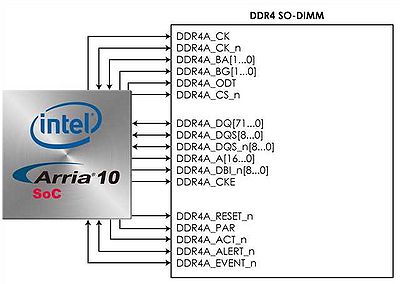
The development board also supports one bank of DDR4 SDRAM SO-DIMM on FPGA side. It is wired to support a maximum capacity of 8GB with a 72-bit data bus. Using differential DQS signaling for the DDR4 SDRAM interfaces, it is capable of running at up to 1067MHz memory clock for a maximum theoretical bandwidth up to 132Gbps. Figure 4-9 shows the connections between the DDR4 SDRAM SODIMM and Arria 10 SoC FPGA. The pin assignments for DDR4 SDRAM SO-DIMM are listed in Table 4-10.
Figure 4-9 The connection between the DDR4 SDRAM SO-DIMM and Arria 10 SoC FPGA
- Table 4-10 The pin assignments for DDR4 SDRAM SO-DIMM
FPGA Pin Number Signal Name Description I/O Standard PIN_AB12 DDR4A_REFCLK_p DDR4 A port Reference Clock p LVDS PIN_AC1 DDR4A_A[0] Address [0] SSTL-12 PIN_AB1 DDR4A_A[1] Address [1] SSTL-12 PIN_AB4 DDR4A_A[2] Address [2] SSTL-12 PIN_AA5 DDR4A_A[3] Address [3] SSTL-12 PIN_AA3 DDR4A_A[4] Address [4] SSTL-12 PIN_AA4 DDR4A_A[5] Address [5] SSTL-12 PIN_Y2 DDR4A_A[6] Address [6] SSTL-12 PIN_AA2 DDR4A_A[7] Address [7] SSTL-12 PIN_AB5 DDR4A_A[8] Address [8] SSTL-12 PIN_AB6 DDR4A_A[9] Address [9] SSTL-12 PIN_W5 DDR4A_A[10] Address [10] SSTL-12 PIN_Y5 DDR4A_A[11] Address [11] SSTL-12 PIN_AA9 DDR4A_A[12] Address [12] SSTL-12 PIN_AB7 DDR4A_A[13] Address [13] SSTL-12 PIN_AA7 DDR4A_A[14] Address [14]/WE_n SSTL-12 PIN_AB10 DDR4A_A[15] Address [15]/CAS_n SSTL-12 PIN_AB11 DDR4A_A[16] Address [16]/RAS_n SSTL-12 PIN_Y7 DDR4A_BA[0] Bank Select [0] SSTL-12 PIN_AB9 DDR4A_BA[1] Bank Select [1] SSTL-12 PIN_AA10 DDR4A_BG[0] Bank Group Select[0] SSTL-12 PIN_AE2 DDR4A_BG[1] Bank Group Select[1] SSTL-12 PIN_AD3 DDR4A_CK Clock p0 DIFFERENTIAL 1.2-V SSTL PIN_AD4 DDR4A_CK_n Clock n0 DIFFERENTIAL 1.2-V SSTL PIN_AC2 DDR4A_CKE Clock Enable pin SSTL-12 PIN_AE8 DDR4A_DQS[0] Data Strobe p[0] DIFFERENTIAL 1.2-V POD PIN_AF7 DDR4A_DQS[1] Data Strobe p[1] DIFFERENTIAL 1.2-V POD PIN_AN1 DDR4A_DQS[2] Data Strobe p[2] DIFFERENTIAL 1.2-V POD PIN_AH2 DDR4A_DQS[3] Data Strobe p[3] DIFFERENTIAL 1.2-V POD PIN_P1 DDR4A_DQS[4] Data Strobe p[4] DIFFERENTIAL 1.2-V POD PIN_J3 DDR4A_DQS[5] Data Strobe p[5] DIFFERENTIAL 1.2-V POD PIN_R5 DDR4A_DQS[6] Data Strobe p[6] DIFFERENTIAL 1.2-V POD PIN_V9 DDR4A_DQS[7] Data Strobe p[7] DIFFERENTIAL 1.2-V POD PIN_V2 DDR4A_DQS[8] Data Strobe p[8] DIFFERENTIAL 1.2-V POD PIN_AD8 DDR4A_DQS_n[0] Data Strobe n[0] DIFFERENTIAL 1.2-V POD PIN_AE7 DDR4A_DQS_n[1] Data Strobe n[1] DIFFERENTIAL 1.2-V POD PIN_AN2 DDR4A_DQS_n[2] Data Strobe n[2] DIFFERENTIAL 1.2-V POD PIN_AH3 DDR4A_DQS_n[3] Data Strobe n[3] DIFFERENTIAL 1.2-V POD PIN_R1 DDR4A_DQS_n[4] Data Strobe n[4] DIFFERENTIAL 1.2-V POD PIN_K3 DDR4A_DQS_n[5] Data Strobe n[5] DIFFERENTIAL 1.2-V POD PIN_R6 DDR4A_DQS_n[6] Data Strobe n[6] DIFFERENTIAL 1.2-V POD PIN_W9 DDR4A_DQS_n[7] Data Strobe n[7] DIFFERENTIAL 1.2-V POD PIN_V3 DDR4A_DQS_n[8] Data Strobe n[8] DIFFERENTIAL 1.2-V POD PIN_AC11 DDR4A_DQ[0] Data [0] 1.2-V POD PIN_AD10 DDR4A_DQ[1] Data [1] 1.2-V POD PIN_AC9 DDR4A_DQ[2] Data [2] 1.2-V POD PIN_AG7 DDR4A_DQ[3] Data [3] 1.2-V POD PIN_AD13 DDR4A_DQ[4] Data [4] 1.2-V POD PIN_AD11 DDR4A_DQ[5] Data [5] 1.2-V POD PIN_AC8 DDR4A_DQ[6] Data [6] 1.2-V POD PIN_AF8 DDR4A_DQ[7] Data [7] 1.2-V POD PIN_AE6 DDR4A_DQ[8] Data [8] 1.2-V POD PIN_AJ6 DDR4A_DQ[9] Data [9] 1.2-V POD PIN_AG6 DDR4A_DQ[10] Data [10] 1.2-V POD PIN_AD6 DDR4A_DQ[11] Data [11] 1.2-V POD PIN_AG5 DDR4A_DQ[12] Data [12] 1.2-V POD PIN_AK5 DDR4A_DQ[13] Data [13] 1.2-V POD PIN_AC7 DDR4A_DQ[14] Data [14] 1.2-V POD PIN_AH6 DDR4A_DQ[15] Data [15] 1.2-V POD PIN_AK1 DDR4A_DQ[16] Data [16] 1.2-V POD PIN_AL4 DDR4A_DQ[17] Data [17] 1.2-V POD PIN_AJ4 DDR4A_DQ[18] Data [18] 1.2-V POD PIN_AM1 DDR4A_DQ[19] Data [19] 1.2-V POD PIN_AK3 DDR4A_DQ[20] Data [20] 1.2-V POD PIN_AL2 DDR4A_DQ[21] Data [21] 1.2-V POD PIN_AJ3 DDR4A_DQ[22] Data [22] 1.2-V POD PIN_AM2 DDR4A_DQ[23] Data [23] 1.2-V POD PIN_AF2 DDR4A_DQ[24] Data [24] 1.2-V POD PIN_AH1 DDR4A_DQ[25] Data [25] 1.2-V POD PIN_AG4 DDR4A_DQ[26] Data [26] 1.2-V POD PIN_AE5 DDR4A_DQ[27] Data [27] 1.2-V POD PIN_AF3 DDR4A_DQ[28] Data [28] 1.2-V POD PIN_AH4 DDR4A_DQ[29] Data [29] 1.2-V POD PIN_AG1 DDR4A_DQ[30] Data [30] 1.2-V POD PIN_AF4 DDR4A_DQ[31] Data [31] 1.2-V POD PIN_K1 DDR4A_DQ[32] Data [32] 1.2-V POD PIN_P4 DDR4A_DQ[33] Data [33] 1.2-V POD PIN_N2 DDR4A_DQ[34] Data [34] 1.2-V POD PIN_K2 DDR4A_DQ[35] Data [35] 1.2-V POD PIN_M2 DDR4A_DQ[36] Data [36] 1.2-V POD PIN_P3 DDR4A_DQ[37] Data [37] 1.2-V POD PIN_N1 DDR4A_DQ[38] Data [38] 1.2-V POD PIN_J1 DDR4A_DQ[39] Data [39] 1.2-V POD PIN_N3 DDR4A_DQ[40] Data [40] 1.2-V POD PIN_P5 DDR4A_DQ[41] Data [41] 1.2-V POD PIN_M5 DDR4A_DQ[42] Data [42] 1.2-V POD PIN_R2 DDR4A_DQ[43] Data [43] 1.2-V POD PIN_N4 DDR4A_DQ[44] Data [44] 1.2-V POD PIN_P6 DDR4A_DQ[45] Data [45] 1.2-V POD PIN_L4 DDR4A_DQ[46] Data [46] 1.2-V POD PIN_R3 DDR4A_DQ[47] Data [47] 1.2-V POD PIN_V6 DDR4A_DQ[48] Data [48] 1.2-V POD PIN_T7 DDR4A_DQ[49] Data [49] 1.2-V POD PIN_U5 DDR4A_DQ[50] Data [50] 1.2-V POD PIN_U7 DDR4A_DQ[51] Data [51] 1.2-V POD PIN_T4 DDR4A_DQ[52] Data [52] 1.2-V POD PIN_W6 DDR4A_DQ[53] Data [53] 1.2-V POD PIN_T3 DDR4A_DQ[54] Data [54] 1.2-V POD PIN_U6 DDR4A_DQ[55] Data [55] 1.2-V POD PIN_W8 DDR4A_DQ[56] Data [56] 1.2-V POD PIN_Y12 DDR4A_DQ[57] Data [57] 1.2-V POD PIN_Y11 DDR4A_DQ[58] Data [58] 1.2-V POD PIN_W10 DDR4A_DQ[59] Data [59] 1.2-V POD PIN_Y13 DDR4A_DQ[60] Data [60] 1.2-V POD PIN_Y8 DDR4A_DQ[61] Data [61] 1.2-V POD PIN_Y10 DDR4A_DQ[62] Data [62] 1.2-V POD PIN_W11 DDR4A_DQ[63] Data [63] 1.2-V POD PIN_V1 DDR4A_DQ[64] Data [64] 1.2-V POD PIN_Y1 DDR4A_DQ[65] Data [65] 1.2-V POD PIN_W3 DDR4A_DQ[66] Data [66] 1.2-V POD PIN_W1 DDR4A_DQ[67] Data [67] 1.2-V POD PIN_Y3 DDR4A_DQ[68] Data [68] 1.2-V POD PIN_W4 DDR4A_DQ[69] Data [69] 1.2-V POD PIN_U1 DDR4A_DQ[70] Data [70] 1.2-V POD PIN_U2 DDR4A_DQ[71] Data [71] 1.2-V POD PIN_AD9 DDR4A_DBI_n[0] Data Bus Inversion [0] 1.2-V POD PIN_AJ5 DDR4A_DBI_n[1] Data Bus Inversion [1] 1.2-V POD PIN_AK2 DDR4A_DBI_n[2] Data Bus Inversion [2] 1.2-V POD PIN_AG2 DDR4A_DBI_n[3] Data Bus Inversion [3] 1.2-V POD PIN_L2 DDR4A_DBI_n[4] Data Bus Inversion [4] 1.2-V POD PIN_L3 DDR4A_DBI_n[5] Data Bus Inversion [5] 1.2-V POD PIN_U4 DDR4A_DBI_n[6] Data Bus Inversion [6] 1.2-V POD PIN_V8 DDR4A_DBI_n[7] Data Bus Inversion [7] 1.2-V POD PIN_V4 DDR4A_DBI_n[8] Data Bus Inversion [8] 1.2-V POD PIN_AE1 DDR4A_CS_n Chip Select SSTL-12 PIN_AE3 DDR4A_RESET_n Chip Reset 1.2 V PIN_AC3 DDR4A_ODT On Die Termination SSTL-12 PIN_AC6 DDR4A_PAR Command and Address Parity Input SSTL-12 PIN_AC12 DDR4A_ALERT_n Register ALERT_n output SSTL-12 PIN_AD1 DDR4A_ACT_n Activation Command Input SSTL-12 PIN_T5 DDR4A_EVENT_n Chip Temperature Event 1.2 V PIN_AD5 DDR4A_AC_R[0] Reserved for QDRII+/RLDRAM3 SSTL-12 PIN_Y6 DDR4A_AC_R[1] Reserved for QDRII+/RLDRAM3 SSTL-12 PIN_AC4 DDR4A_C[0] Reserved for QDRII+/RLDRAM3 SSTL-12 PIN_AB2 DDR4A_C[1] Reserved for QDRII+/RLDRAM3 SSTL-12 PIN_AA8 DDR4A_RZQ External reference ball for output drive calibration 1.2 V
The DDR4 SDRAM SO-DIMM socket can support many kinds of memory devices, such as standard DDR4 SO-DIMM with ECC up to 8GB at 1067MHz, Terasic QDRII+ module with DDR4 SO-DIMM interface, Terasic RLDRAM3 module with DDR4 SO-DIMM interface, as shown in Figure 4-10, Figure 4-11 and Figure 4-12.
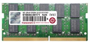
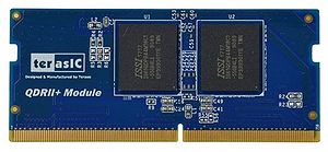
Figure 4-10 Standard DDR4 SO-DIMM with ECC Figure 4-11 Terasic QDRII+ module with DDR4 SO-DIMM interface
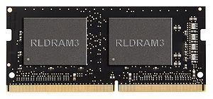
Figure 4-12 Terasic RLDRAM3 module with DDR4 SO-DIMM interface
