DE10-Advance Hardware Manual revC Chapter5 UART to USB
From Terasic Wiki
5.3 UART to USB
The board has one UART interface connected for communication with the HPS. This interface doesn’t support HW flow control signals. The physical interface is implemented by UART-USB onboard bridge from a FT232R chip to the host with an USB Mini-B connector. More information about the chip is available on the manufacturer’s website, or in the directory \Datasheets\UART TO USB of DE10-Advanced system CD. Figure 5-2 shows the connections between the HPS, FT232R chip, and the USB Mini-B connector. Table 5-4 lists the pin assignment of UART interface connected to the HPS.
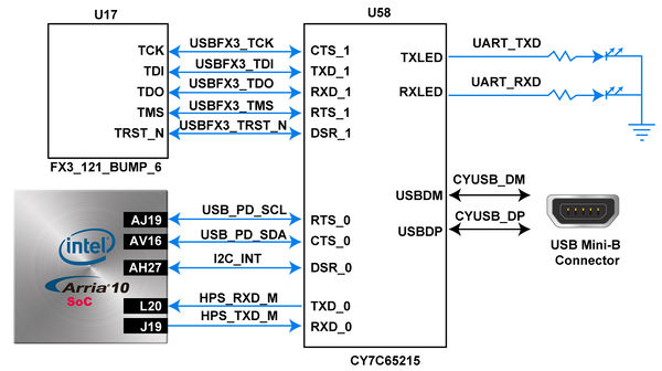
- Figure 5-2 Connections between the HPS and USB Mini-B connector
- Table 5-4 Pin Assignment of UART Interface

Signal Name FPGA Pin Number Description I/O Standard USB_PD_SCL PIN_AJ19 I2C Serial Clock 1.8V USB_PD_SDA PIN_AV16 I2C Serial Data 1.8V I2C_INT PIN_AH27 inter-integrated circuit 1.8V HPS_RXD_M PIN_L20 HPS UART Receiver 1.8V HPS_TXD_M PIN_J19 HPS UART Transmitter 1.8V