Documents
| 標題 | 版本 | 大小 | 日期 | 下載 |
|---|---|---|---|---|
| Data Conversion HSMC reference manual | 1.0.1 | 712(KB) | 2011-07-01 |
CD-ROM
| 標題 | 版本 | 大小 | 日期 | 下載 |
|---|---|---|---|---|
| 高速数位类比转换子板 CD | 1.0.1 | 2011-07-01 |
友晶創新所發表之範例程式碼,基於免費分享之原則,不提供任何形式的講解或修改。如需進一步範例程式碼講解或修改的協助,我們將轉至「設計服務部門」評估。
本授權條款允許使用者於使用所有友晶及 Intel 開發板時,得以重製、散布、傳輸以及修改友晶創新提供的原始碼,但不得為商業目的之使用。使用時必須於引用處表彰友晶創新 (Terasic Inc.) 之商號。
Transmission Demo
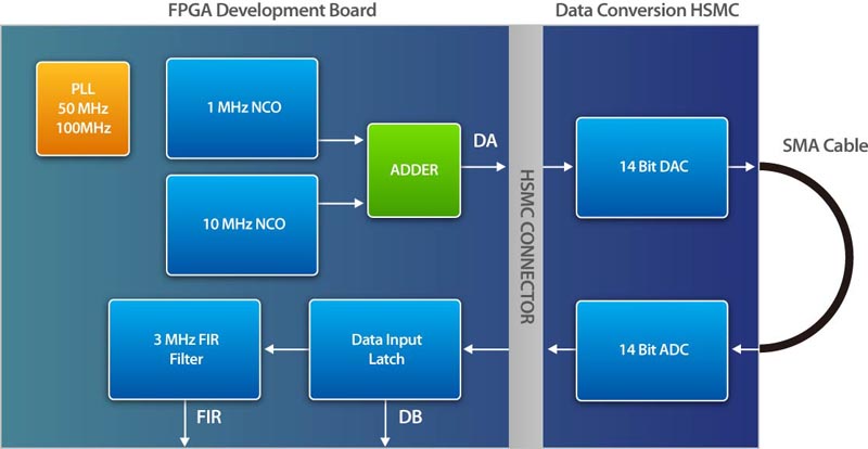
The Data Conversion HSMC CD includes a reference design which contains two sine waves that are generated by two instances of the Altera numerically controlled oscillator (NCO) MegaCore. One of these oscillators is running at 10 times the frequency of the other, but both of them have the same amplitude with each one covering 13 bits of dynamic range. From these blocks, the two sine waves output are converted from two’s complement binary to unsigned binary format which then are added together. The combined sine wave signal of 14-bits dynamic range is sent to a 14-bit D/A converter. The analog output of a D/A converter is connected via SMA Cable with the analog input of a 14-bit A/D converter. The A/D converter’s digital output is looped back to the FPGA device. The A/D is configured by the dip switches to deliver the data in unsigned format. The converted loopback data is captured by an instance of the SignalTap® II logic analyzer in the design for display and analysis.
The following figure below shows a high-level view of the reference design and how it interacts with the D/A and A/D converters on the Data Conversion HSMC in the following sections.
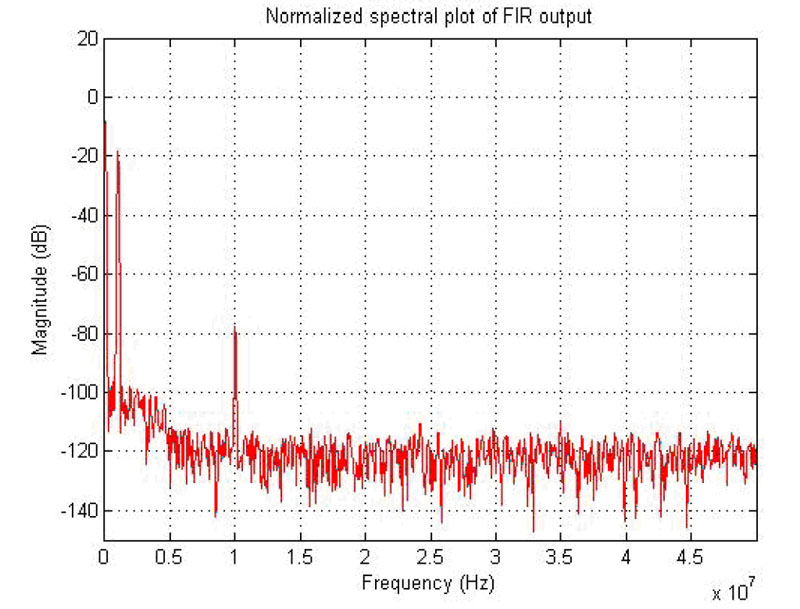
You can use MATLAB software to analyze the data.
The following figure below is generated using SignalTap to capture and analyze data.