DE10 Advance revC demo: Auto Fan Speed Control
From Terasic Wiki
AutoFan RTL Demonstration Descriptions
This demonstration shows you how to adjust the fan rotation speed according to the FPGA chip temperature value.
The fan rotation speed is adjusted according to the process shown in Figure 2-1 below.
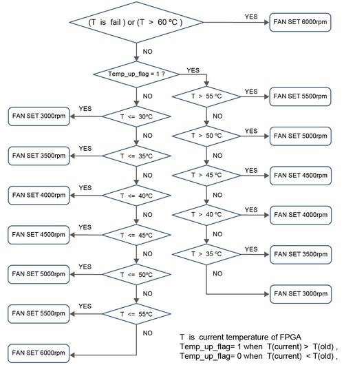
- Figure 2-1 Fan rotation speed determination process

- Function Block Diagram
Figure 2-2 Shows the Function block diagram of the AutoFan demonstration. This design has two main parts. The one is an I2C controller(FAN_TEMP_I2C), which can be used to read the temperature value of the DE10-Advanced Temperature Sensor IC (TMP441) and to set the Fan Controller IC (MAX6650) register for controlling the fan rotation speed. Both the Temperature Sensor and the Fan Controller use the same I2C bus. The Temperature Sensor I2C Slave-Address is 0x38, the Fan Controller I2C Slave-Address is 0x90. The other one is a judgment controller (FAN_ONOFF), which can determine the fan rotation speed value according to the process in Figure 2-1. In this demonstration, you can use the two seven segments to display the FPGA temperature value and the fan rotation speed value(rpm). All module functions are described as below:
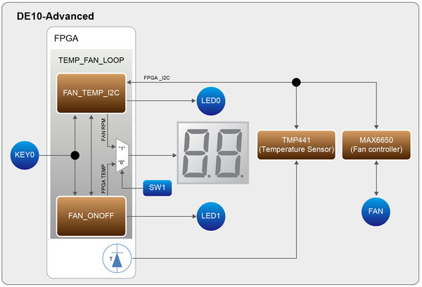
- Figure 2-2 Block diagram of the AutoFan design

FAN_TEMP_I2C: this module can read the temperature value converted by the DE10-Advanced Temperature Sensor IC (TMP441) and to set the Fan Controller IC (MAX6650) register for controlling the fan rotation speed.
FAN_ONOFF: according to the FPGA temperature value (which output from FAN_TEMP_I2C module) and the process in Figure 4-1, this module can determine the fan rotation speed value(rpm) and output it to the FAN_TEMP_I2C module.
KEY0: which is used as system RESET function. When pressing KEY0, the two modules(FAN_TEMP_I2C and FAN_ONOFF) will reset.
SW1: set the two seven segments to display the fan rotation speed or the FPGA temperature. SW1=1, display the current fan rotation speed value(display the thousands and the hundreds, in decimal), SW1=0, display FPGA temperature value.
The following are the descriptions of the platforms’ set up, as well as the test steps.
AutoFan RTL Demonstration Setup
- Hardware Setting Up
As shown in Figure 2-3:
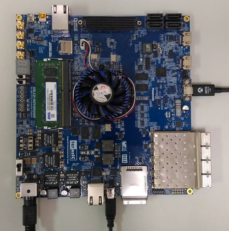
- Figure 2-3 AutoFan demo hardware setting up

- Design Tools
- Quartus Prime 18.0 Standard Edition
- Demonstration Source Code
- Quartus project directory: AutoFan
- Bitstream used: DE10_Advanced.sof
- Demonstration Batch File
- Demo batch file folder: demonstrations\AutoFan\demo_batch
- Demonstration Setup
- Connect the DE10_Advanced USB Blaster II port (J20) to the host PC with a USB cable and install the USB-Blaster II driver if necessary.
- Plug the 12V adapter to DE10_Advanced Board.
- Power on the DE10_Advanced board.
- Execute the demo batch file “test.bat” from the directory \FPGA\AutoFan\demo_batch.The fan rotation speed value is finally stabilized at RPM=3000. set SW1=1, the two seven segments will display the current fan rotation speed value (display the thousands and the hundreds, in decimal), set SW1=0, the two seven segments will display the FPGA temperature value (display the tens and the ones, in decimal). LED[1:0] functions in this demonstration are: when the Fan rotation speed is abnormal (ex, fan doesn’t rotate). LED0 lights up, when the FPGA temperature value is greater than 50ºC, LED1 lights up.
Table 2-1 Summarizes the functional keys and details of each LED status.
- Table 2-1 The functional keys of the AutoFan demonstration
Name Description KEY0 System reset, press the KEY0 to reset the system SW1 Control the two seven segments HEX[1:0]
SW1=1, display the current fan rotation speed value(display the thousands and the hundreds, in decimal)
SW1=0, display the FPGA temperature value(display the tens and the ones, in decimal)HEX[1:0] Display two decimal numbers LED0 When the Fan rotation speed is abnormal (ex, fan doesn’t rotate), LED0 lights up LED1 When the FPGA temperature value is greater than 50ºC, LED1 lights up