DE10 Advance revC demo: Develop the C Code
From Terasic Wiki
This section introduces how to design an ARM C program to control the led_pio PIO controller. SoC EDS is used to compile the C project. For ARM program to control the led_pio PIO component, led_pio address is required. The Linux built-in driver ‘/dev/mem’ and mmap system-call are used to map the physical base address of led_pio component to a virtual address which can be directly accessed by Linux application software.
Contents |
LED_PIO Address
The led_pio component information is required for ARM C program as the program will attempt to control the component. This section describes how to get led_pio’s address.
You can get led_pio’s address from qsys’s Address Map dialog box. Figure 4-4 shows led_pio’s address in Address Map. You can define a macro for the address when you use it.
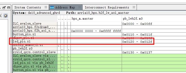
- Figure 4-4 Pio led address in Qsys’s Address Map

Map LED_PIO Address
This section will describe how to map the led_pio physical address into a virtual address which is accessible by an application software. Figure 4-5 shows the C program to derive the virtual address of led_pio base address. First, open system-call is used to open memory device driver “/dev/mem”, and then the mmap system-call is used to map HPS physical address into a virtual address represented by the void pointer variable virtual_base. The demo code maps the physical base address (HW_REGS_BASE = 0xfc000000) of the peripheral region into a based virtual address virtual_base. For any controller in the peripheral region, users can calculate their virtual address by adding their offset relative to the peripheral region to the based virtual address virtual_base. Based on the rule, the virtual address of led_pio can be calculated by adding the below two offset addresses to virtual_base.
- Offset address of Lightweight HPS-to-FPGA AXI bus relative to HPS base address
- Offset address of Pio_led relative to Lightweight HPS-to-FPGA AXI bus
The first offset address is 0xff200000 which is defined as a constant ALT_FPGA_BRIDGE_LWH2F_OFST in the header hps.h. The hps.h is a header of SoC EDS. It is located in the Quartus installation folder: D:\IntelFPGA\18.0\embedded\ip\altera\hps\altera_hps\hwlib\include\soc_a10\socal.
The second offset address is 0x120 which is led_pio’s address defined as LED_PIO_BASE in the C code file.
The virtual address of led_pio is represented by a void pointer variable h2p_lw_led_addr. Application program can directly use the pointer variable to access the registers in the controller of LED_PIO.
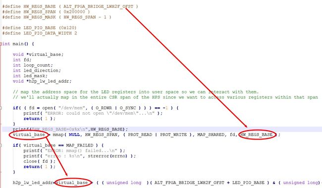
- Figure 4-5 LED PIO memory map code

LED Control
C programmers need to understand the Register Map of the PIO core for LED_PIO before they can control it. Figure 4-6 shows the Register Map for the PIO Core. Each register is 32-bit width. For detail information, please refer to the datasheet of PIO Core. For led control, we just need to write output value to the offset 0 register. Because the led on DE10-Advancedd is low active, writing a value 0x00000003 to the offset 0 register will turn off the two LEDs. Writing a value 0x00000000 to the offset 0 register will turn on the two LEDs. In C program, writing a value 0x00000000 to the offset 0 register of led_pio can be implemented as:
- *(uint32_t *) h2p_lw_led_addr= 0x00000000;
The state will assign the void pointer to a uint32_t pointer, so C compiler knows write a 32-bit value 0x00000000 to the virtual address h2p_lw_led_addr.
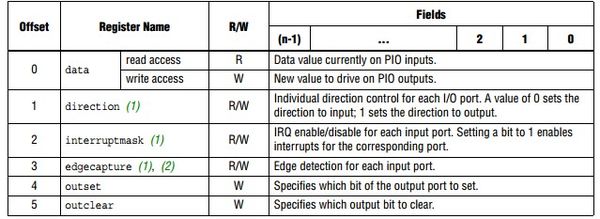
- Figure 4-6 Register Map of PIO Core

Main Program
In the main program, the LED is controlled to perform LED light shifting operation as shown in Figure 4-7. When finishing 60 times of shift cycle, the program will be terminated.
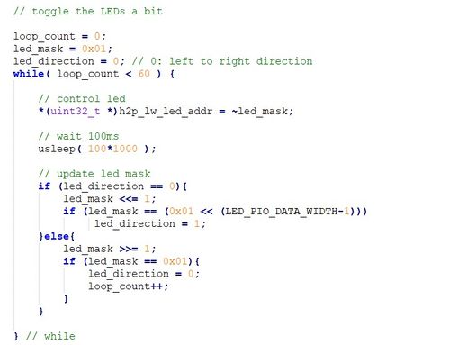
- Figure 4-7 C Program for LED Shift Operation

Makefile and compile
Figure 4-8 shows the content of Makefile for this C project. The program includes the head files provided by SoC EDS. In the Makefile, ARM-linux cross-compile also be specified.
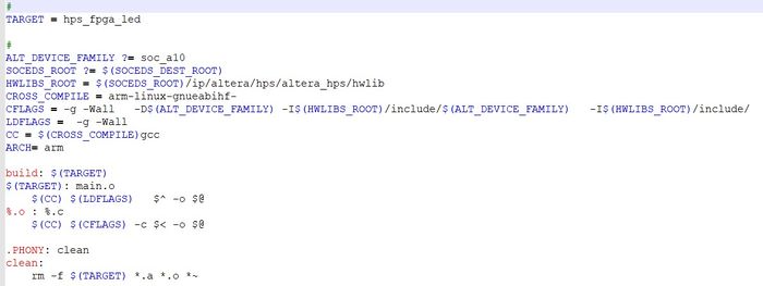
- Figure 4-8 Makefile content

To compile the project, type “make” in the command shell as shown in Figure 4-9. Then, type “ls” to check the generated ARM execution file “hps_fpga_led”.
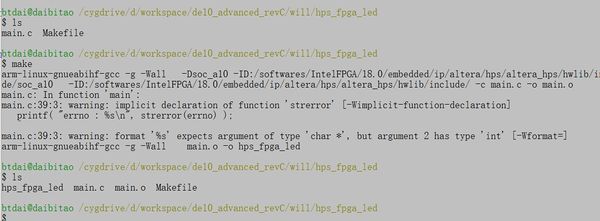
- Figure 4-9 ARM C Project Compilation

Execute the Demo
To execute the demo, please boot the Linux from the SD-card in DE10-Advanced. Copy the execution file “hps_fpga_led” to the Linux directory, and type “chmod +x hps_fpga_led” to add execution attribute to the execute file. Then, type “./ hps_fpga_led” to launch the ARM program. The LED[1:0] on DE10-Advanced will be expected to perform 60 times of LED light shift operation, and then the program is terminated.
For details about booting the Linux from SD-card, please refer to the document: Getting_Started_Guide.pdf