DE10 Advance revC demo: HPS GPIO Header
From Terasic Wiki
This demonstration shows how to use the system call with built-in GPIO driver to implement HPS GPIO Header’s loopback. The built-in GPIO driver is included the DE10-Advanced LXDE VNC Desktop BSP.
Contents |
Function Block Diagram
Figure 3-7 shows the function block diagram of the HPS GPIO Header loopback demonstration. The built-in GPIO driver offers interfaces, to which the application can use system call such as open, read, write to access. We can export the gpio port that we want to control, and when we export the gpio port, the linux system will create attribute files of the gpio port in the location “/sys/class/gpio/gpioN/” (N is the gpio port’ number). There are two attribute files we need to know : value and direction. The value file is used to read and write value to the gpio port (the value can only be “0” or “1”); the direction file is used to set the gpio port’s data direction.
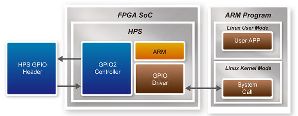
- Figure 3-7 Function block diagram of HPS GPIO Header demonstration

Function Implement
In the c code project, we need to implement five functions, described as following:
- int gpio_export(unsigned int gpio);
The gpio_export function is used to export the gpio port with the specified port number as parameter.
- int gpio_unexport(unsigned int gpio);
The gpio_unexport function is used to disable the exported gpio port with the specified port number as parameter.
- int gpio_set_dir(unsigned int gpio, unsigned int out_flag);
The gpio_set_dir function is used to set the gpio port’s data direction , the parameter “gpio” is the port number you want to configure and the parameter “out_flag” is value to set. Number “1” for data out, and “0” for data in. when you use this api, it will wirte “in” or “out” to the gpio port’s direction file. The default value of direction file is “in”.
- int gpio_set_value(unsigned int gpio, unsigned int value);
The gpio_set_value function is used to write data to the gpio port. The parameter “gpio” is the port number you want to configure and then parameter “value” is the data you want to write. The value can only be “0” or “1”. When you use the api, it will write data to the gpio port’s value file.
- int gpio_get_value(unsigned int gpio, unsigned int *value);
The gpio_get_value function is used to read the gpio port’s data, and the parameter “value” is used to store the value that you read. The parameter “gpio” is the gpio port that you want to read.
All of the functions are implemented in the c code file, you can get more details from the c code file.
Loopback Implement
There are four gpio ports used to loopback. They are IO8, IO9, IO10, IO11. The Loopback includes two test patterns, the differences between them are data direction and test data value. In test one, we set IO 8 up to 11 as “out”,”in”,”out”,”in” respectively, and the test data is a 32-bit value “0x1234f0f0”.
Described below are the loopback’s implementation procedure:
- Export gpios
- Set gpios’s data direction
- Data write and read back
- Verify the received data
Figure 3-8 shows the procedure in c code, you can find it’s very clear.
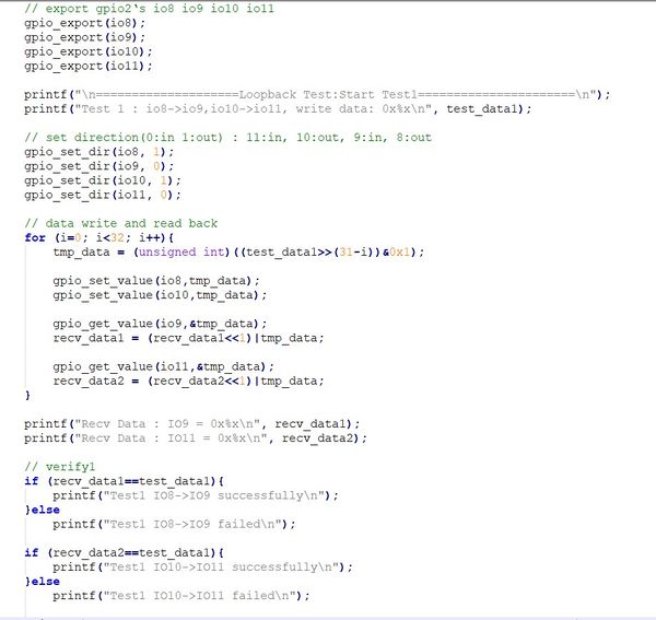
- Figure 3-8 loopback implemented in c code

Demonstration Source Code
- Build tool: SoC EDS V18.0
- Project directory: \Demonstration\SoC\hps_gpio_loopback
- Binary file: hps_gpio_loopback
- Build command: make ('make clean' to remove all temporal files)
- Execute command: ./hps_gpio_loopback
Demonstration Setup
- Use jumper cap connect IO8 to IO9 and IO10 to IO11 in hps gpio header(J36) on the DE10-Advanced board. Figure 3-9 shows the pin location below.
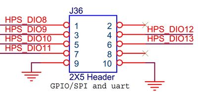
- Figure 3-9 GPIO Header Pin location
- Connect a USB cable to the USB-to-UART connector (J27) on the DE10-Advanced board and the host PC.
- Copy the executable file "hps_gpo_loopback" into the microSD card under the "/home/root" folder in Linux. (DE10-Advanced LXDE has pre-installed this code, so users can skip this copy action.)
- Insert the LXDE booting micro SD card into the DE10-Advanced board.
- Power on the DE10-Advanced board.
- Launch Putty to establish the connection between the UART port of DE10-Advanced board and the host PC.
- In the Putty UART terminal, type "root" to login LXDE Linux.with pressing Enter as password.
- Type "cd hps_gpio_loopback” to into the folder and type “./hps_gpio_loopback” in the UART terminal to start the program.
- You will see the loopback test successfully in the Putty UART terminal as shown in Figure 3-10.
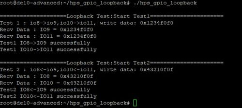
- Figure 3-10 Loopback test successfully

