DE10 Advance revC demo: Nios II control for Programmable PLL/Temperature/Power/9-axis
From Terasic Wiki
This demonstration shows how to use the Nios II processor to program two programmable oscillators (CDCM6208 and TXC) on the FPGA board, how to measure the power consumption based on the built-in power measure circuit. The demonstration also includes a function of monitoring system temperature with the on-board temperature sensor, and 3-axis gyroscope, 3-axis accelerometer, and 3-axis magnetometer output with the on-board MPU-9250 MotionTracking device.
System Block Diagram
Figure 1-1 shows the system block diagram of this demonstration. The system requires a 50 MHz clock provided from the board. The five peripherals (including temperature sensor, power monitor, CDCM6208, TXC, and MPU-9250) are all controlled by Nios II through the PIO controller, and all of them are programmed through I2C protocol which is implemented in the C code. The I2C pins from chip are connected to Qsys System Interconnect Fabric through PIO controllers. The Nios II program toggles the PIO controller to implement the I2C protocol. The Nios II program is running in the on-chip memory.

- Figure 1-1 Block diagram of the Nios II Basic Demonstration
The program provides a menu in nios-terminal, as shown in Figure 1-2 to provide an interactive interface. With the menu, users can perform the test for the temperatures sensor, power monitor, external programmable PLL and 9-axis outputs. Note, pressing ‘ENTER’ should be followed with the choice number.

- Figure 1-2 Menu of Demo Program
In temperature test, the program will display local temperature and remote temperature. The remote temperature is the FPGA temperature, and the local temperature is the board temperature where the temperature sensor located.
A power monitor IC (LTC2945) embedded on the board can monitor Arria10 real-time current and power. This IC can work out current/power value as multiplier and divider are embedded in it. There is a sense resistor R176 (0.006 Ω) for LTC2945 in the circuit, when power on the DE10-Advanced board, there will be a voltage drop (named ∆SENSE Voltage) on R176. Based on sense resistors, the program of power monitor can calculate the associated voltage, current and power consumption from the LTC2945 through the I2C interface. Please note the device I2C address is 0xD4.
The MPU-9250 consists of two dies, one die houses the 3-axis gyroscope and 3-axis accelerometer, and the other die houses the a-axis magnetometer. Similarly, the MPU-9250 provides complete 9-axis output through the I2C interface.
In the external PLL programming test, the program will program the PLL first, and subsequently will use TERASIC QSYS custom CLOCK_COUNTER IP to count the clock count in a specified period to check whether the output frequency is changed as configured. For CDCM6208 programming, the program can control the CDCM6208 to configure the output frequency of SATA/PCIE/DDR4A/DDR4B/DDR4H REFCLK according to your choice. Please note the device I2C address is 0xA8. For TXC programming, the program can control the TXC to configure the output frequency of HDMI/SFP+/FMC/DP/USB REFCLK according to your choice. There are five TXC’s ICs for clock generator, divided into two group, TXCA and TXCB. The HDMI and SFP+ reference clock generators share the same I2C bus, REFCLK0_SCL/REFCLK0_SDA, and are grouped into TXCA. The FMC, DP, and USB reference clock generators also share the same I2C bus , REFCLK1_SCL/REFCLK1_SDA, and are grouped into TXCB.
Demonstration File Locations
- Hardware project directory: Basic_Demo
- Bitstream used: Basic_Demo.sof
- Software project directory: Basic_Demo \software
- Demo batch file : Basic_Demo\demo_batch\test.bat, test.sh
Demonstration Setup and Instructions
- Make sure Quartus Prime and Nios II are installed on your PC.
- Power on the FPGA board.
- Use the USB Cable to connect your PC and the FPGA board and install USB Blaster II driver if necessary.
- Execute the demo batch file “test.bat” under the batch file folder, Basic_Demo\demo_batch.
- After the Nios II program is downloaded and executed successfully, a prompt message will be displayed in nios2-terminal.
- For temperature test, please input key ‘0’ and press ‘Enter’ in the nios-terminal, , as shown in Figure 1-3.
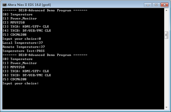
- Figure 1-3 Temperature Demo
- For power monitor test, please input key ‘1’ and press ‘Enter’ in the nios-terminal, the Nios II console will display the values of voltage, current and power as shown in Figure 1-4
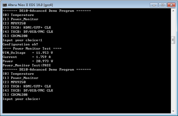
- Figure 1-4 power monitor Demo
- For 9-axis test, please input key ‘2’ and press ‘Enter’ in the nios-terminal, the Nios II console will display the values of 9-axis as shown in Figure 1-5.
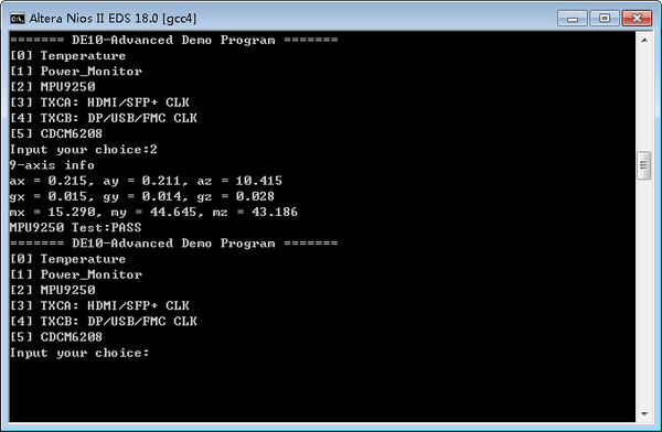
- Figure 1-5 MPU-9250 Demo
- For programmable PLL TXCA test, please input key ‘3’ and press ‘Enter’ in the nios-terminal first, then select the desired output frequency of HDMI/SFP+ REFCLK, as shown in Figure 1-6.
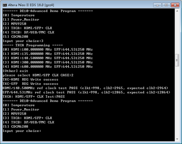
- Figure 1-6 TXCA Demo
- For programmable PLL TXCB test, please input key ‘4’ and press ‘Enter’ in the nios-terminal first, then select the desired output frequency of DP/USB/FMC REFCLK, as shown in Figure 1-7
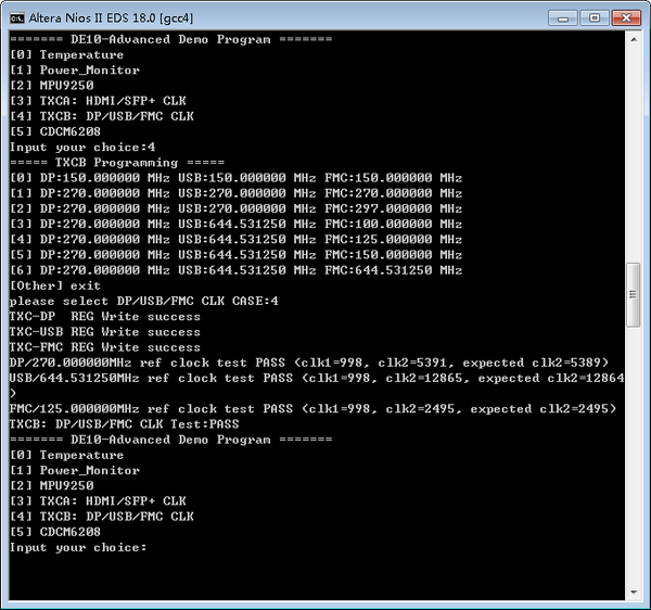
- Figure 1-7 TXCB Demo
- For programmable PLL CDCM6208 test, please input key ‘5’ and press ‘Enter’ in the nios-terminal first, then select the desired output frequency of SATA/PCIE/DDR4A/DDR4B/DDR4H REFCLK, as shown in Figure 1-8.
-
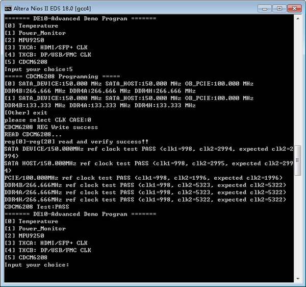
- Figure 1-8 CDCM6208 Demo
-


