DE10 Advance revC demo: Socket Server
From Terasic Wiki
The Arria 10 device on the DE10_Advanced consists of built-in serializer/deserializer (SERDES) circuitry for high-speed LVDS interfaces to support Gigabit Ethernet. Ethernet has been the dominant networking protocol providing a simple, cost-effective option for backbone and server connectivity. Gigabit Ethernet builds on top of the Ethernet protocol with speed up to 1000 Mbps, or 1 gigabit per second (Gbps). In this demonstration, we will illustrate how to create a simple socket server generated in Nios II using the Gigabit Ethernet devices equipped on the DE10_Advanced board.
Contents |
System Block Diagram
As indicated in the block diagram in Figure 2-1, the Nios II processor is used to communicate with the client via Marvell 88E1111 Ethernet Transceiver.

- Figure 2-1 Block diagram of the Socket Server Demonstration
Part of Nios II, NicheStack TCP/IP Network Stack is a software suite of networking protocols designed to provide an optimal solution for designing network-connected embedded devices with the Nios II processor. A telnet client application is used to communicate with the Simple Socket Server issuing commands over a TCP/IP socket to the Ethernet-connected NicheStack TCP/IP Stack running on the DE10_Advanced with a Simple Socket Server. The Simple Socket Server continues to listen for commands on a TCP/IP port and operates the DE10_Advanced according to the commands from the telnet client. NicheStack TCP/IP stack uses the MicroC/OS-II RTOS multithreaded environment to provide immediate access to a stack for Ethernet connectivity for the Nios II processor. The Nios II processor system contains an Ethernet interface, or media access control (MAC)
How the Ethernet demonstration is built
In this following section we describe how to build the demonstration through the QSYS. The QSYS system includes the CPU processor, On-Chip memory, JTAG UART, system ID, timer, Triple-Speed Ethernet, Scatter-Gather DMA Controllers and peripherals which are linked together contained in the Nios II hardware system that are used when building a project. Figure 2-2 presents the overall setup of the QSYS from the Ethernet Simple Socket Server project.

- Figure 2-2 QSYS for Ethernet Simple Socket Server
In the Triple-Speed Ethernet IP Core configuration, the interface is set to SGMII as well as using the internal FIFO shown in Figure 2-3.

- Figure 2-3 Triple-Speed Ethernet core configurations
In the MAC options section, the MDIO module is included that controls the PHY Management Module associated with the MAC block. The host clock divisor is to divide the MAC control register interface clock to produce the MDC clock output on the MDIO interface. The MAC control register interface clock frequency is 100 MHz and the desired MDC clock frequency is 2.5 MHz, a host clock divisor of 40 should be used. Once the Triple-Speed Ethernet IP configuration has been set and necessary hardware connections has been made click on ‘Generate’ to build the interconnect logic automatically.
In this following section we will describe the steps to create the Simple Socket Server using Nios II. We create a new project in Nios II using the project template, Simple Socket Server shown in Figure 2-4. The PTF file created using the SOPC builder in Quartus II is used in the Select Target Hardware section.

- Figure 2-4 Nios II project simple socket server
Overview
The Simple Socket Server uses the industry standard sockets interface to TCP/IP. It uses DHCP protocol to requests a valid IP from the Gateway. During the device initialization process, the NichStack TCP/IP Stack system code calls get_mac_add() and get_ip_add() to get the MAC and IP addresses for the network interface. Once the MAC address is generated, Autonegotiation is initiated where both connected devices, the Ethernet (Marvel 88E1111) and Gateway devices broadcasts its transmission parameters, speed and duplex mode. By default, the MAC interface for the Ethernet device is set to SGMII. In this demonstration, we are using SGMII MAC interface which can be configured through the management interface of the 88E1111 Ethernet device. Once the link is established an IP address is assigned to the Ethernet device along with the port number. Through TCP and port number, the demonstration uses Telnet client to establish connection with the Simple Socket Server, where it is continuously listening on the port. Once the connection is established between the Telnet client and Simple Socket Server, the Telnet client is able to send packets which are received by the Nios II processor and through the Simple Socket Server it will send server command to the DE10_Advanced. The packet sent contains LED command which is extracted and dispatched to the LED command queue for processing by the LED management tasks.
Figure 2-5 shows the software architecture of the Nios program for the Simple Socket Server. The top block containing the Nios II processor and the necessary hardware to be implemented into the DE10_Advaned board. The software device drivers contain the necessary device drivers needed for Ethernet and other hardware components to functions. The HAL API block provides the interface for the software device drivers, while the MicroC/OS-II provdes communication services to the NichStack and the Simple Socket Server. The NicheStack TCP/IP stack software block provides networking services to the application where it contains tasks for Simple Socket Server and also LED management.

- Figure 2-5 Nios program software architecture
Running the demonstration
- Design Tools
- Quartus Prime 17.0 Standard Edition
- Nios II Software Build Tools for Eclipse 17.0
- Demonstration Source Code
- Quartus Project directory: Socket_Server
- Nios II Eclipse: Socket_Server \software
- Nios II Project Compilation
- Before you attempt to compile the reference design under Nios II Eclipse, make sure the project is cleaned first by clicking ‘Clean’ from the ‘Project’ menu of Nios II Eclipse.
- Demonstration Batch File
- Demo Batch File Folder: Socket_Server \demo_batch
- The demo batch file includes following files:
- Batch File for USB-Blaseter II: test.bat, test.sh
- FPGA Configure File: DE10_Advanced_socket_server.sof
- Nios II Program: socket_server.elf
- Demonstration Setup
- Please follow below procedures to setup the demonstration.
- Make sure Quartus Prime and Nios II are installed on your PC.
- Use USB Cable to connect PC and the FPGA board and install USB Blaster II driver if necessary.
- Connect the etherent to Router or network switch with DHCP .
- Power on the FPGA board.
- Execute the demo batch file “test.bat” under the folder “NIOS_DDR4\demo_batch”.
- After Nios II program is downloaded and executed successfully, a prompt message will be displayed in nios2-terminal. where the IP address and port numbers are assigned as shown below in Figure2-6.
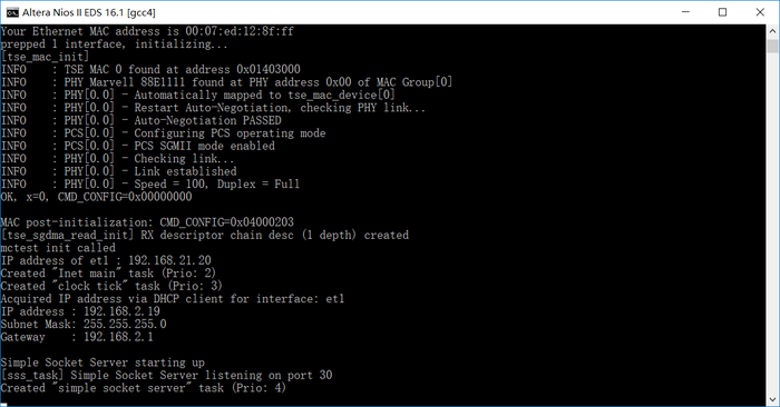
- Figure 2-6 Simple socket server
- To establish connection, start the telnet client session by executing open_telnet.bat file and include the IP address assigned by the DHCP server-provided IP along with the port number as shown below in Figure 2-7.
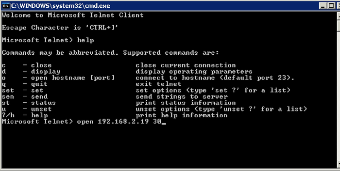
- Figure 2-7 Telnet Client
- From the Simple Socket Server Menu, enter the commands in the telnet session. Entering a number from zero through one followed by a return causes the corresponding the LEDs (LED0-LED1) to toggle on or off on the DE10_Advanced board

