DE10 Advance revC demo: USB Type-C DisplayPort Alternate Mode
From Terasic Wiki
This section introduces how to implement a DisplayPort Source based on USB Type-C DisplayPort Alternate Mode. The demo includes two major parts: DisplayPort and USB Type-C.
For DisplayPort design, DisplayPort Intel FPGA IP is used to generate DisplayPort TX video. The DisplayPort design is refer to the document :Arria 10 DisplayPort Design Example using on board connector (TX Only).
For USB Type-C, system need to monitor the information sent from the USB Type-C Port Controller CYPD3125 (EZ-PD CCG3). From the sent information, system can know whether the plug-in device is a DisplayPort monitor and the DP lane number is 4 or 2, and system have to configure the DisplayPort crossbar switch so the FPGA transceiver signals can be routed to the type-c port correctly.
The Qaurtus Project USBC_DP_4K is designed for 4K monitor, and USBC_DP_FullHD is design for Full HD Monitor. If your Type-C monitor only supports Full HD, please use the USB_DP_FullHD for the demo setup.
System Block Diagram
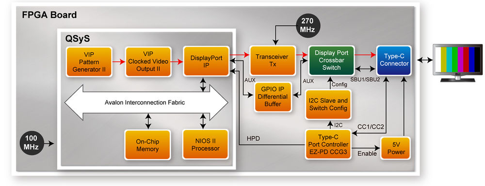
Figure 2-1 shows the system block diagram for the DisplayPort Demo. When a Type-C monitor is plugged into the Type-C Connector, the Type-C Port Controller (EZ-PD CCG3) will enable 5V power for the monitor. When a Type-C device is plug-in or removed from the Type-C connector, the CCG3 will notify FPGA through the IC2 interface. CCG3 will sends one byte data to 0 offset address in the I2C Slave Port. The meaning of the data is shown in Table 2-1. If attached device is a DisplayPort monitor, then DisplayPort crossbar switch is configured so the transceivers signals are routed to the type-c connector correctly.
For DisplayPort design, the Hot Plug Detect (HPD) causes the DisplayPort source to initialize the link via AUX channel. The DisplayPort IP generates parallel Video data and FPGA transceivers are used to serial the video data. For 4K video data, 4 TX transceivers are used with reference clock 270 MHz. For Full HD video data, 4 or 2 TX transceivers are used. The input video data for DisplayPort IP is generated by VIP Test Pattern Generator II IP and VIP Clocked Video Output II IP.
In the system, a Nios II processor is used to control the DisplayPort IP. The Nios II Processor is running on on-chip memory with 100Mhz.
- Figure 2-1 Block Diagram of DisplayPort Demo
- Table 2-1 Information sent by CCG3
Data[6:5] Description 0 No Device is attached 1 Only USB 3.1 Device is attached 2 4 Lane DisplayPort monitor is attached 3 USB and 2 Lane DisplayPort monitor is attached
Data[4] Description 0 Cable is normal 1 Cable is flip
Demonstration File Locations
- For 4K Video Output:
- Hardware project directory: USBC_DP_4K
- Bitstream used: DE10_Adavnced_golden_top.sof
- Nios II Program: dp_demo_test.elf
- Demo batch file : USBC_DP_4K\demo_batch\test.bat
- For Full-HD Video Output:
- Hardware project directory: USBC_DP_FullHD
- Bitstream used: DE10_Adavnced_golden_top.sof
- Nios II Program: dp_demo_test.elf
- Demo batch file : USBC_DP_FullHD\demo_batch\test.bat
- Note, Quartus 17.0 Standard is used for these demonstration design. Use Quartus 18.0 could make malfunction.
- Demonstration Setup and Instructions
- Make sure Quartus Prime is installed on your PC.
- Power on the FPGA board.
- Use the Mini USB Cable to connect your PC and the FPGA board and install USB Blaster II driver if necessary.
- Execute test.bat under the demo_batch folder.
- Connect USB Type-C Connector (J2) to a 4K Type-C Monitor (or Full HD Type-C Monitor) via a Type-C Cable.
- You will see a color bar pattern on the Type-C Monitor.
